
Low voltage device for the generation of plasma discharge to operate a supersonic or hypersonic apparatus
- Summary
- Abstract
- Description
- Claims
- Application Information
AI Technical Summary
Benefits of technology
Problems solved by technology
Method used
Image

Examples
Embodiment Construction
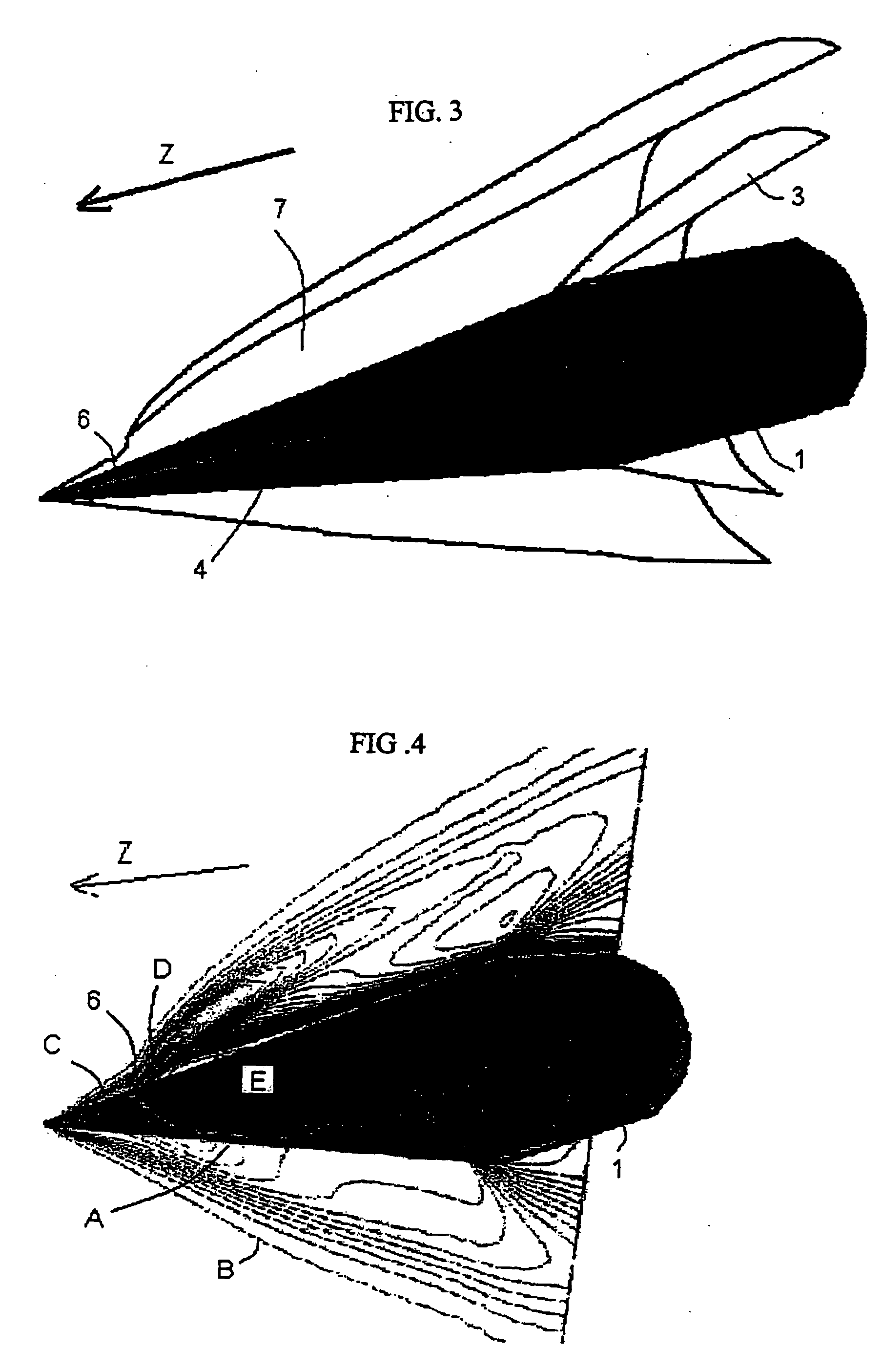
[0042] During flight, an expansion wave is produced upstream of a hypervelocity projectile's nose. When the projectile is flying along a straight-line trajectory, the pressures distributed over its surface are balanced and the expansion wave has symmetries following the shape of the projectile. In the case of a projectile having a conical nose, the wave attaches to the tip of the cone and is conical in shape.
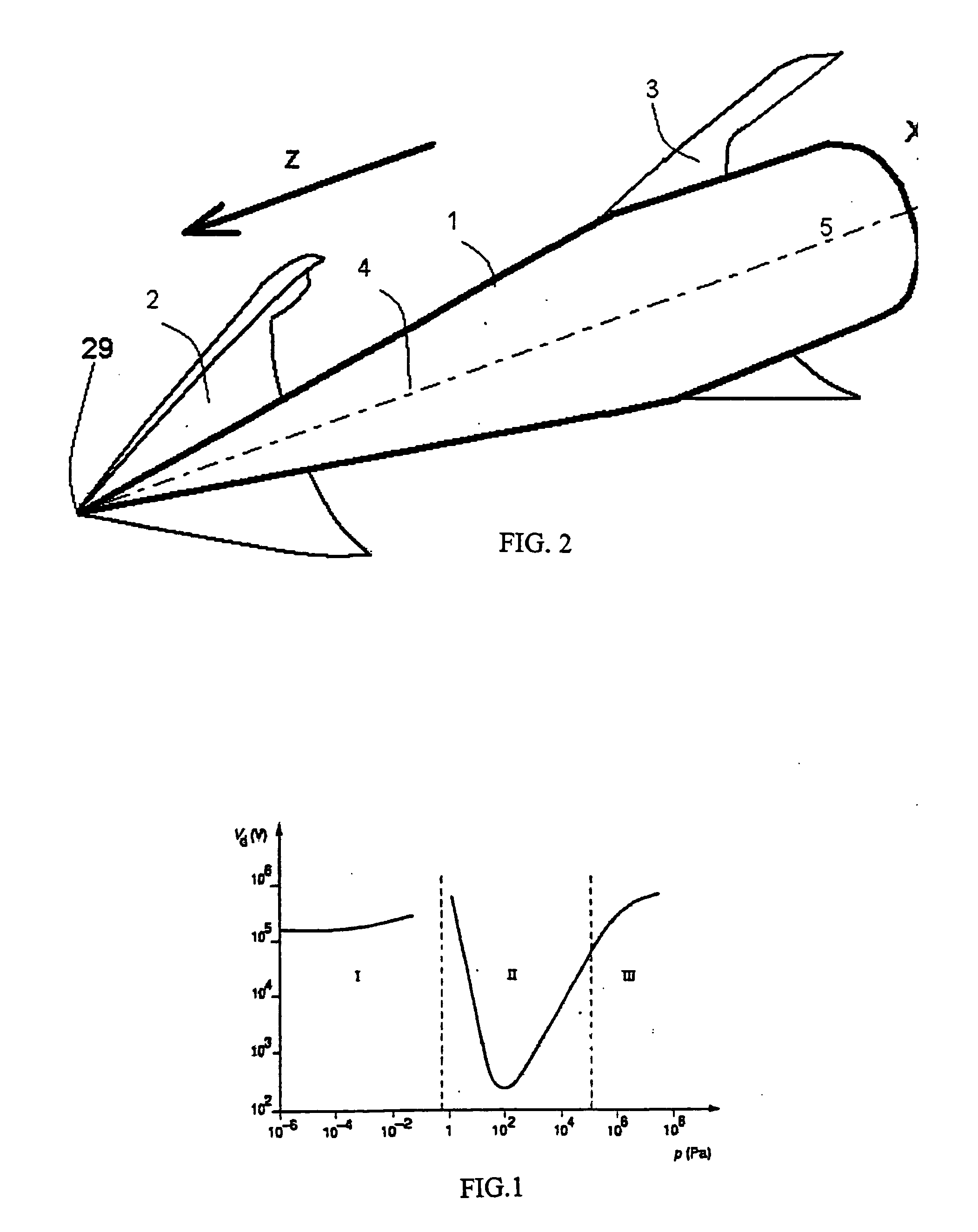
[0043]FIG. 2 shows the result of a digital simulation of a projectile (e.g., projectile 1) with lengthwise axis X flying at supersonic speed in the direction Z of the arrow. It shows integrally projectile 1 and half of two other surfaces 2 and 3. The projectile has a conical front part 4 and a cylindrical rear part 5. Surfaces 2 and 3 characterize a constant pressure in the flow. Surface 2 attached to the tip of the projectile represents the surface of the conical expansion wave while surface 3 attached to the discontinuity of the projectile surface (cone-cylinder junction) cha...
PUM
 Abstract
Description
Claims
Application Information