
Motor controlling device

Inactive Publication Date: 2007-08-30
HONDA MOTOR CO LTD
View PDF12 Cites 6 Cited by
  • Summary
  • Abstract
  • Description
  • Claims
  • Application Information

AI Technical Summary

Benefits of technology

[0015]Therefore, unlike the case where the conventional motor controlling device described above that controls the amount of energization by the PWM control that involves changing the directions of energization of the armatures, useless energization of the armatures can be avoided. As a result, heat generation by the armatures and the switching elements due to such useless energization can be avoided, and the heat generated by the armatures and the switching elements when the alternating-current motor operates can be reduced.
[0017]According to the present invention, the alternating-current motor used as a joint motor for a leg of a legged walking robot has to output a high torque to make a sequence of walking movements while maintaining a proper posture of the legged walking robot. To this end, the amount of energization of the armatures of the alternating-current motor increases. In addition, since the motor controlling device according to the present invention is housed in the housing of the legged walking robot along with the alternating-current motor, the heat generated by the alternating-current motor and the first to fourth switching elements of the H bridge circuits tends to be confined in the housing. Thus, the energization control means performs the PWM control to reduce the heat generated by the alternating-current motor and the first to fourth switching elements, thereby preventing degradation of the performance of the alternating-current motor and the first to fourth switching elements due to the temperature increase and thus degradation of the walking performance of the legged walking robot.
[0019]According to the present invention, the alternating-current motor is disposed between the engine and the transmission. Thus, air convection around the alternating-current motor is hard to occur. In addition, the heat generated by the engine is transferred to the alternating-current motor not only from the outside thereof but also from the inside thereof via the output shaft of the engine. As a result, the temperature of the alternating-current motor tends to increase. Thus, the energization control means performs the PWM control to reduce the heat generated by the alternating-current motor and the first to fourth switching elements, thereby preventing degradation of the performance of the alternating-current motor and the first to fourth switching elements due to the temperature increase and thus degradation of the running performance of the hybrid vehicle.

Problems solved by technology

In addition, when the rotational speed of the alternating-current motor 200 is low, a large current flows through the part of one phase for a long time, and therefore, there is a problem that the heat generated by the switching elements and armature increases.

Method used


Image

  • Motor controlling device
  • Motor controlling device
  • Motor controlling device

Examples


Embodiment Construction

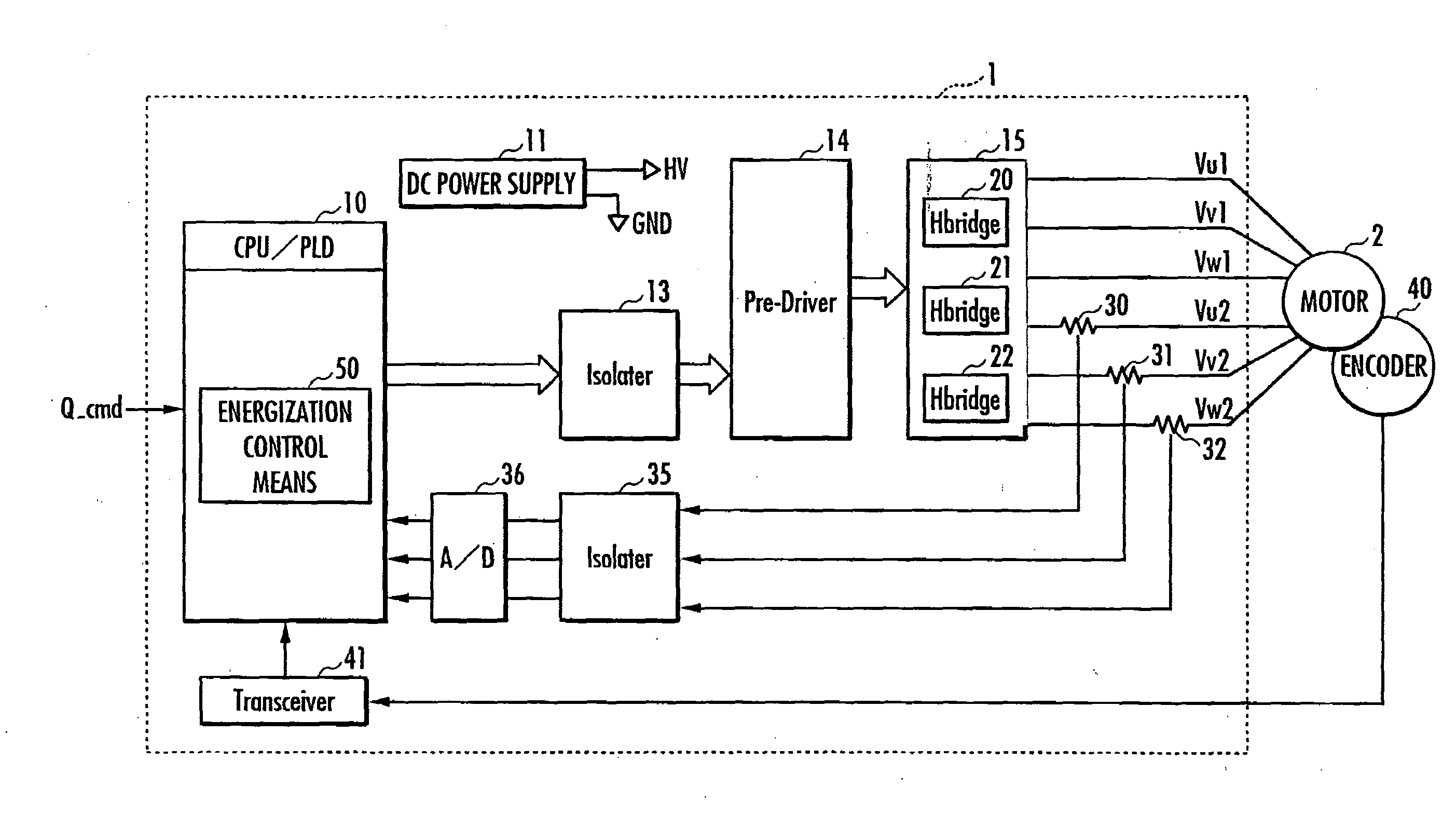
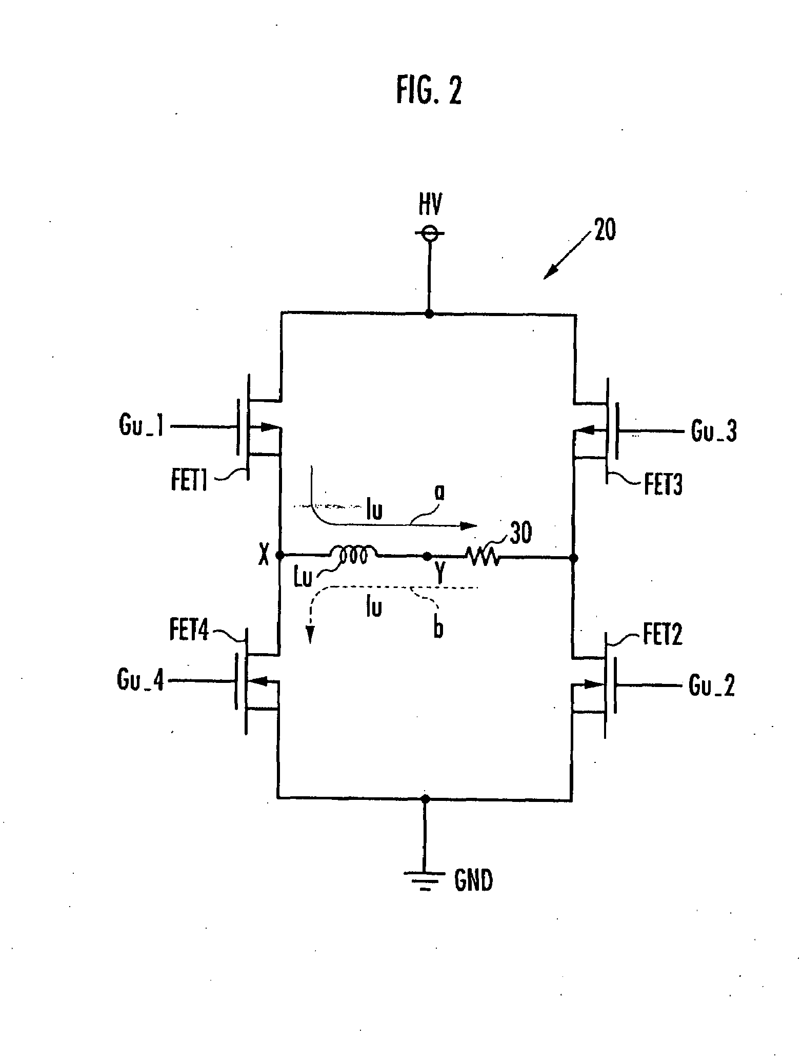
[0029]An embodiment of the present invention will be described with reference to FIGS. 1 to 6. FIG. 1 is a diagram showing a configuration of a motor controlling device according to the present invention, FIG. 2 is a diagram showing a configuration of an H bridge circuit shown in FIG. 1, FIG. 3 shows an appearance of a legged walking robot on which the motor controlling device shown in FIG. 1 and an alternating-current motor are mounted, FIG. 4 includes graphs for illustrating the amount of energization of the alternating-current motor under the PWM control, FIG. 5 is a graph for comparing the heat generated by an alternating-current motor controlled by the motor controlling device shown in FIG. 1 with the heat generated by an alternating-current motor controlled a conventional motor controlling device, and FIG. 6 is a diagram showing a hybrid vehicle to which the present invention is applied.

[0030]Referring to FIG. 1, a motor controlling device 1 is designed to control the amount o...


PUM


Abstract

To provide a motor controlling device that reduces heat generated by an armature and switching elements when an alternating motor is activated. A motor controlling device includes: an H bridge circuit 20 that has FET1 to FET4 that connect and disconnect a high potential end HV and a low potential end GND of a direct-current power supply to and from an armature Lu; and an energization control unit for controlling the amount of energization of the armature Lu by the PWM control that involves changing the ratio, in a predetermined control cycle, between an energization control period, in which the FET1 and the FET2 are turned on and the FET3 and the FET4 are turned off, or the FET3 and the FET4 are turned on and the FET1 and the FET2 are turned off, and a non-energization control period, in which the FET1 and the FET3 are turned on and the FET2 and the FET4 are turned off, or the FET2 and the FET4 are turned on and the FET1 and the FET3 are turned off.

Description

BACKGROUND OF THE INVENTION[0001]1. Field of the Invention[0002]The present invention relates to control of the amount of energization of an alternating-current motor. In particular, it relates to a motor controlling device that controls the amount of energization of an alternating-current motor by turning on and off switching elements forming an H bridge.[0003]2. Description of the Related Art[0004]Conventional motor controlling devices for a three-phase alternating-current motor, which is a typical alternating-current motor, are configured as shown in FIG. 7 and control the amount of energization of the three-phase alternating-current motor by supplying current command values balanced among the three phases (the U phase, the V phase and the W phase) to armatures 230, 231, 232. Specifically, a PWM circuit 241 and a base drive circuit 240 control the amount of energization by the PWM control that involves changing the ratio between the directions of energization of the armatures 230...

Claims


Application Information

Patent Timeline
IPC IPC(8): H02P1/18H02P7/06G05F1/10
CPCH02P27/08
Inventor MISUMI, TAKESHIKOBASHI, SHINICHIRO
Owner HONDA MOTOR CO LTD
Learn More