Magnification varying optical system and image taking apparatus

a technology which is applied in the field of image taking apparatus, can solve the problems of inability to say that the magnification varying optical system of patent document 3 sufficiently meets, and the straight optical system is unfit to be mounted on dscs, etc., and achieves the effect of downsizing the magnification

Active Publication Date: 2007-08-30
KONICA MINOLTA OPTO
View PDF2 Cites 19 Cited by
  • Summary
  • Abstract
  • Description
  • Claims
  • Application Information

AI Technical Summary

Benefits of technology

[0013]The present invention is made to solve the above-mentioned problem, and an object thereof is to provide a high-performance and downsized magnification varying optical system and an image taking apparatus having same.

Problems solved by technology

It can be said that magnification varying optical systems in which a plurality of lens units are arranged in a line, so-called straight optical systems like those of Patent Documents 1 and 2 are unfit to be mounted on DSCs.
That is, it cannot be said that the magnification varying optical system of Patent Document 3 sufficiently satisfies the requirements, size reduction and performance enhancement.

Method used


Image

  • Magnification varying optical system and image taking apparatus
  • Magnification varying optical system and image taking apparatus
  • Magnification varying optical system and image taking apparatus

Examples


first embodiment

[0042]A description of an embodiment of the present invention with reference to the drawings is as follows:

[1. Digital Still Camera]

[0043]FIG. 17 is a block diagram showing the structure of a digital still camera (DSC) 29 which is an example of the image taking apparatus of the present invention.

[0044]As shown in FIG. 17, the DSC 29 includes a magnification varying optical system OS, a flash FL, an optical system driver 13, an image sensor SR, a signal processor 14, a display 15, a recorder 16, a recording medium 17, an operation portion 18, and a controller 19.

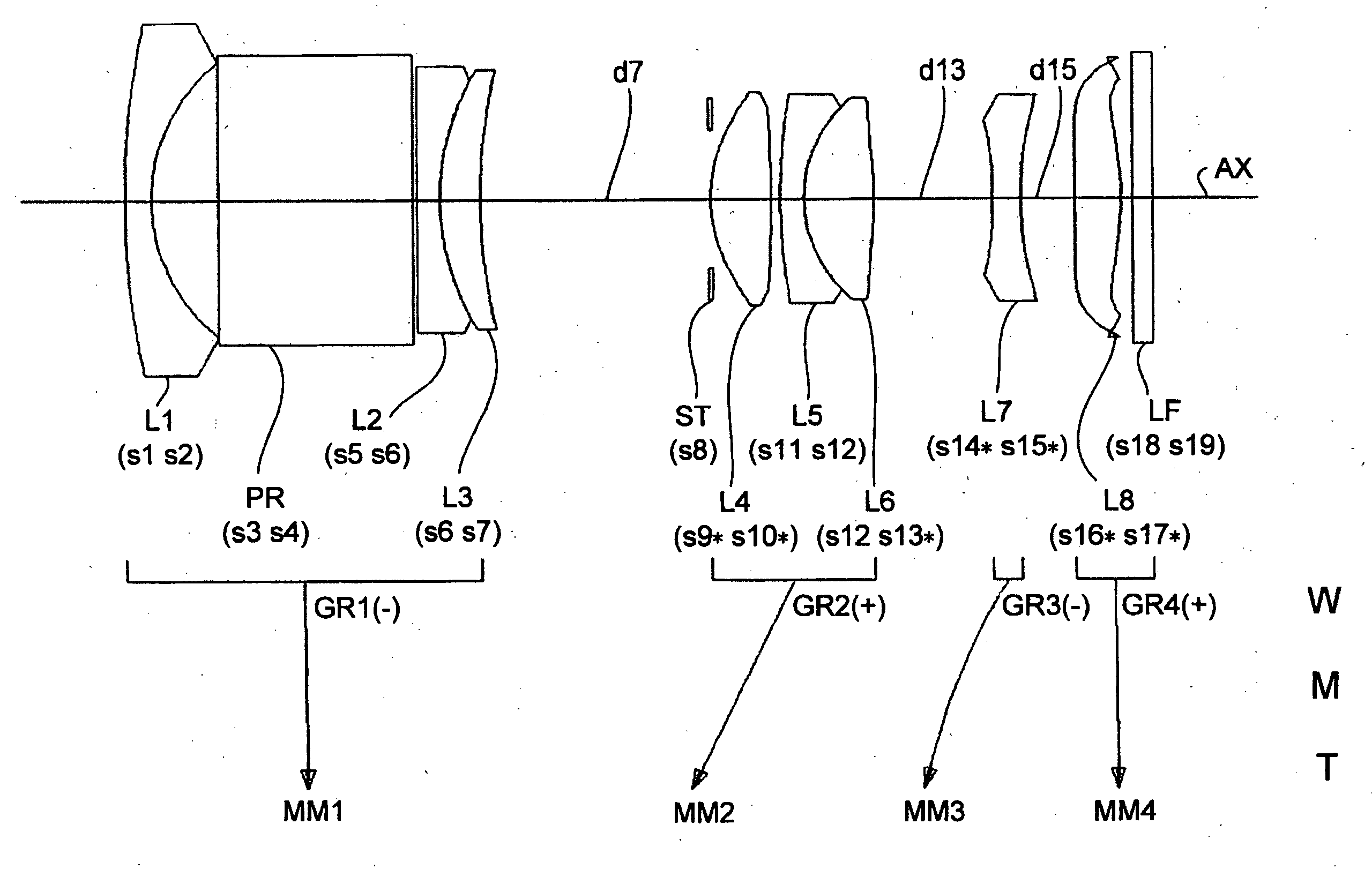
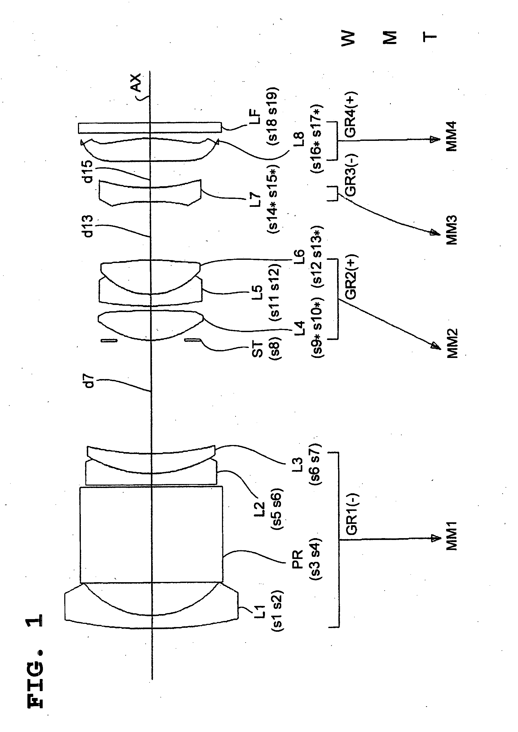
[0045]The magnification varying optical system OS directs light from the object to be image-taken (object side) to the image sensor SR, and forms the light into an image on the light receiving plane (image plane) of the image sensor SR. Therefore, this magnification varying optical system OS may be expressed as an image forming optical system or an image taking optical system. Details of the magnification varying optical syst...


PUM


Abstract

A magnification varying optical system that directs light from an object to an image sensor includes in order from the object side: a first lens unit having negative optical power and including an optical axis changing element that changes the optical axis; a second lens unit having positive optical power and including three lens elements; a third lens unit having negative optical power; and a fourth lens unit having positive optical power. In this magnification varying optical system, in magnification varying from the wide-angle end to the telephoto end, the first lens unit is stationary, the distance from the first lens unit to the second lens unit decreases, and the distance from the third lens unit to the fourth lens unit increases. The magnification varying optical system satisfies the specified conditions.

Description

[0001]This application is based on the application No. 2006-053527 filed in Japan Feb. 28, 2006, the entire content of which is hereby incorporated by reference.BACKGROUND OF THE INVENTION[0002]1. Field of the Invention[0003]The present invention relates to a magnification varying optical system used for optical units and the like, and to an image taking apparatus having this magnification varying optical system.[0004]2. Description of the Related Art[0005]In recent years, with the spread of personal computers (PCs), digital still cameras (image taking apparatuses) with which images can be easily taken have been widespread. Such digital still cameras (DSCs) are also required to be smaller in size and thickness and to be higher in performance, for example, to have a high zooming function or a high aberration correcting function like cameras using silver halide film. For this reason, lens optical systems mounted on digital still cameras such as magnification varying optical systems ar...

Claims


Application Information

Patent Timeline
Patent Type & Authority Applications(United States)
IPC IPC(8): G02B15/14
CPCG02B15/177G02B9/34G02B15/144511
Inventor KOHNO, TETSUOTERADA, MAMORUSOUMA, YOSHIHITO
Owner KONICA MINOLTA OPTO
Why Eureka
Try Eureka