Communication Terminal Apparatus And Wireless Transmission Method

Active Publication Date: 2007-08-30
OPTIS WIRELESS TECH LLC
View PDF12 Cites 37 Cited by
  • Summary
  • Abstract
  • Description
  • Claims
  • Application Information

AI Technical Summary

Benefits of technology

[0010] According to the communication terminal apparatus according to the present invention, an access request signal is transmitted or retransmitted using a sub-channel selected from a group of sub-channels defined by a class of frequency, so that it is possible to reduce the probability of occurrence of collision of access request signals. As a result, according to the communication terminal apparatus according to the present invention, the number of retransmissions of the access request signal can be reduced, so that it is possible to start communication in a short time, and suppress reduction in throughput in the radio communication system. Further, according to the communication terminal apparatus according to the present invention, it is possible to improve the communication quality of packet communication having exacting delay requirement, such as speech communication and video transmission.
[0011] Moreover, according to the communication terminal apparatus according to the present invention, the scheme of selecting a sub-channel can be changed in the case of first transmitting an access request signal and in the case of retransmitt

Problems solved by technology

In such a radio communication system, when a plurality of communication terminal apparatuses transmit access request signals concurrently using the same resource on the RACH, collision of access request signals occu

Method used


Image

  • Communication Terminal Apparatus And Wireless Transmission Method
  • Communication Terminal Apparatus And Wireless Transmission Method
  • Communication Terminal Apparatus And Wireless Transmission Method

Examples


Example

Embodiment 1

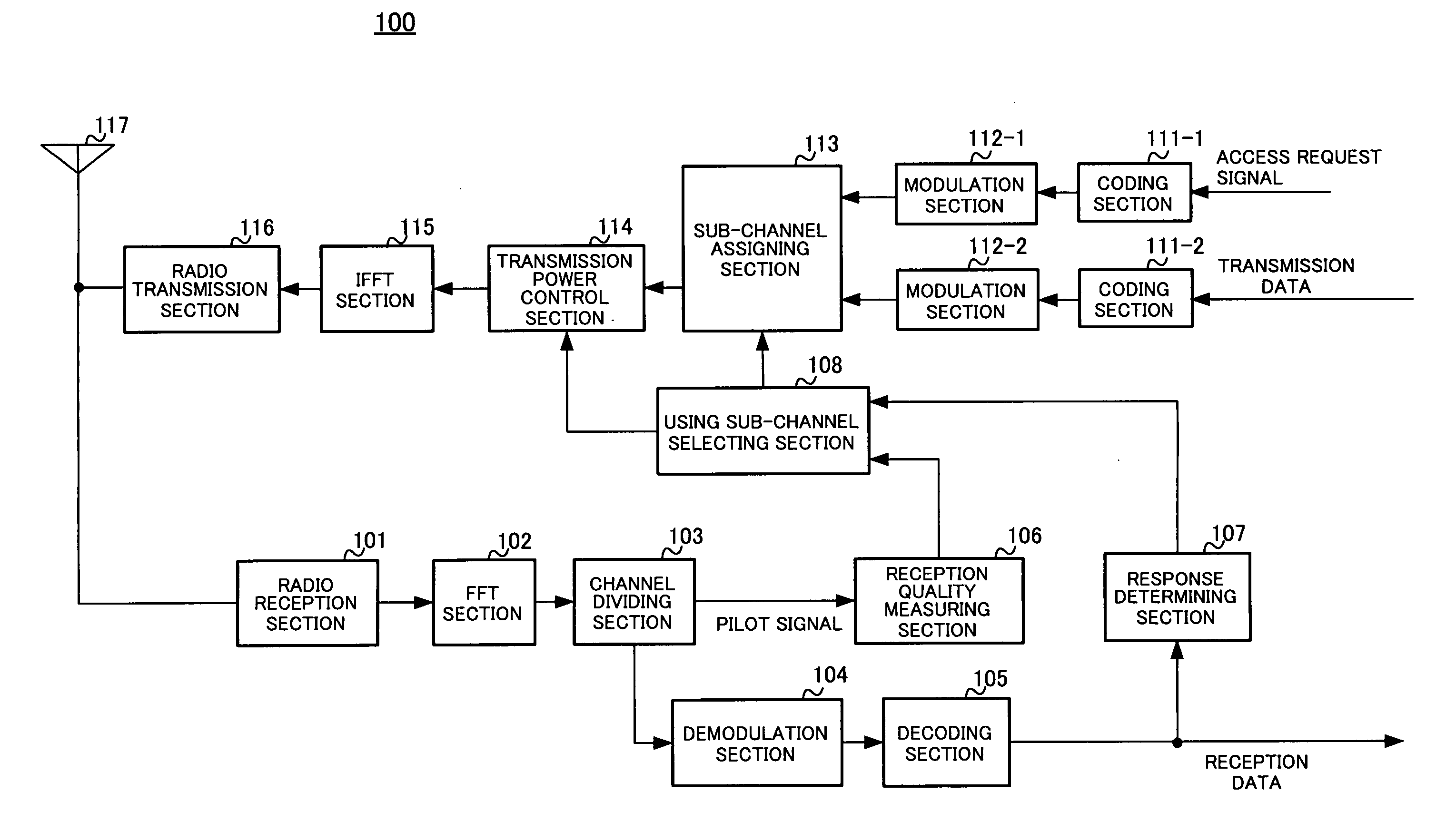
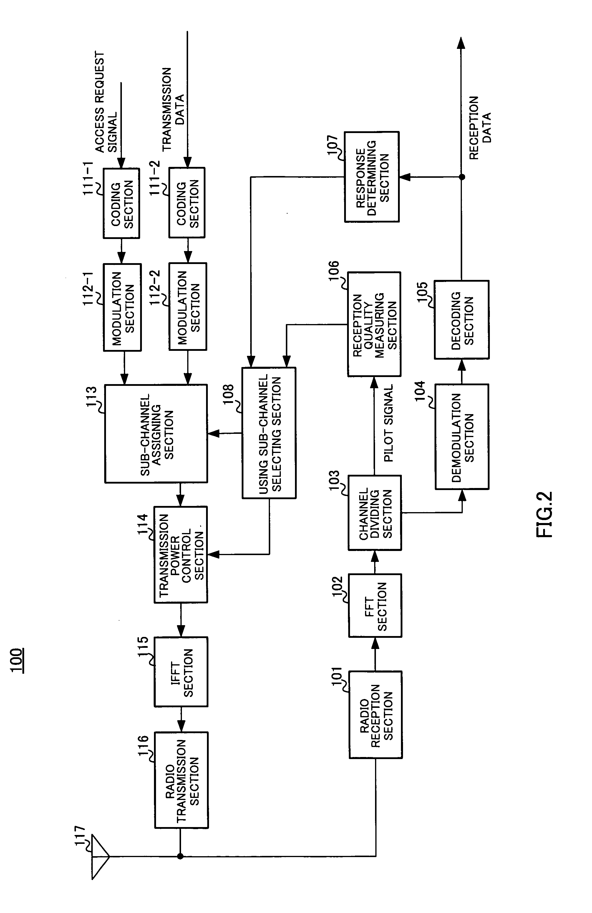
[0030] Embodiment 1 of the present invention describes the case where an OFDM signal is transmitted or received in a time division duplex (TDD) scheme, as an example. FIG. 2 is a block diagram illustrating a configuration of communication terminal apparatus 100 according to Embodiment 1 of the present invention. Communication terminal apparatus 100 has radio reception section 101, FFT (Fast Fourier Transform) section 102, channel dividing section 103, demodulation section 104, decoding section 105, reception quality measuring section 106, response determining section 107, using sub-channel selecting section 108, coding sections 111-1 and 111-2, modulation sections 112-1 and 112-2, sub-channel assigning section 113, transmission power control section 114, IFFT (Inverse Fast Fourier Transform) section 115, radio transmission section 116 and antenna element 117.

[0031] Radio reception section 101 receives a pilot signal, access permission signal and the like transmitted by...

Example

Embodiment 2

[0052]FIG. 4 is a block diagram illustrating a configuration of communication terminal apparatus 300 according to Embodiment 2 of the present invention. Communication terminal apparatus 300 has using sub-channel selecting section 308 instead of using sub-channel selecting section 108, and threshold setting section 321 between response determining section 107 and using sub-channel selecting section 308 in communication terminal apparatus 100 according to Embodiment 1.

[0053] Based on the reception quality for each sub-channel reported from reception quality measuring section 106, using sub-channel selecting section 308 randomly selects one from a group of sub-channels with the reception quality more than or equal to a threshold reported from threshold setting section 321, and reports the selected sub-channel to sub-channel assigning section 113. Further, using sub-channel selecting section 308 reports a transmission power level associated with the reception quality of th...

Example

Embodiment 3

[0064]FIG. 7 is a block diagram illustrating a configuration of communication terminal apparatus 600 according to Embodiment 3 of the present invention. Communication terminal apparatus 600 has using sub-channel selecting section 608 instead of using sub-channel selecting section 108, and has number-of-selection candidates setting section 632 between response determining section 107 and using sub-channel selecting section 608 in communication terminal apparatus 100 according to Embodiment 1.

[0065] Based on the reception quality for each sub-channel reported from reception quality measuring section 106, using sub-channel selecting section 608 randomly selects one from a group of sub-channels with higher reception quality where the number of sub-channels is within the sum of M and n reported from number-of-selection candidates setting section 632, reports the selected sub-channel to sub-channel assigning section 113, and further reports a transmission power level associa...


PUM


Abstract

A communication terminal apparatus that exhibits a shorter time period required until a start of communication and causes the throughput in the wireless communication system to be less reduced. In this apparatus, when the number, N, of retransmissions notified by a response determining part (107) is zero, a subchannel-to-be-used selecting part (108) selects a subchannel, among others, which exhibits the highest order one of the reception qualities of the subchannels notified by a reception quality determining part (106), and then notifies the selected subchannel to a subchannel allocating part (113). When the notified number, N, of retransmissions is one or more, the response determining part (107) selects a subchannel which exhibits the N-th lower order reception quality than the highest order reception quality, based on the reception qualities of the subchannels notified by the reception quality determining part (106) for a pilot signal received after a transmission of the latest access request signal, and then notifies the selected subchannel to the subchannel allocating part (113).

Description

TECHNICAL FIELD [0001] The present invention relates to a communication terminal apparatus that performs radio communication with a base station apparatus and the like, and a radio transmission method. BACKGROUND ART [0002] Conventionally, in a radio communication system, when a communication terminal apparatus such as a mobile telephone starts radio communication such as packet transmission, the communication terminal apparatus receives a pilot signal periodically transmitted from the base station apparatus, performs open-loop transmission power control (OL-TPC) on an access request signal based on reception quality of the pilot signal, and transmits the access request signal to the base station apparatus using a random access channel (RACH), and when receiving the access request signal, the base station apparatus transmits an access permission signal to the communication terminal apparatus using a forward access channel (FACH). Then, after receiving the access permission signal, t...

Claims


Application Information

Patent Timeline
IPC IPC(8): H04J3/16H04J11/00H04W48/16H04L27/01H04W36/16H04W52/50H04W72/02H04W74/04H04W74/08H04W76/02H04W84/12H04W88/02
CPCH04W36/16H04W52/50H04W74/0866H04W72/085H04W72/02H04W72/542H04W74/08
Inventor NISHIO, AKIHIKO
Owner OPTIS WIRELESS TECH LLC
Why Eureka
Try Eureka