Method For Characterizing An Optical Fiber Link

a technology of optical fiber and characterization method, which is applied in the direction of polarization reflection meter, transmission, testing of fibre optic/optical waveguide devices, etc., can solve the problems of not allowing the complete determination of pmd, not allowing quantification of pmd, and the most serious limitation factor of high-speed optical communication system

Inactive Publication Date: 2007-08-30
FACULTE POLYTECHN DE MONS
View PDF6 Cites 22 Cited by
  • Summary
  • Abstract
  • Description
  • Claims
  • Application Information

AI Technical Summary

Problems solved by technology

Polarisation mode dispersion (PMD) has therefore become the most serious limiting factor in high-speed optical communication systems.
There exist several measurement techniques of PMD, but they only allow for measuring the global value and do not give information about the distribution of PMD along the fibre length.
Most of them allow a measurement of the beat length distribution along an optical link and, therefore, do not allow the complete determination of the PMD.
This technique does not allow quantification of the PMD, but enables to obtain distributed information about the level of PMD.
The method as described above has some important drawbacks and limitations.
In practice, the set-up is characterised by some imperfections, which cause a distortion of the ideal POTDR signal.
Therefore the method as such cannot be directly applied.
The POTDR signal is also affected by noise: detector noise and residual coherence noise, which adds a series of minima and maxima to the POTDR trace.
The final value of the measured PMD can therefore be erroneous.

Method used


Image

  • Method For Characterizing An Optical Fiber Link
  • Method For Characterizing An Optical Fiber Link
  • Method For Characterizing An Optical Fiber Link

Examples


Embodiment Construction

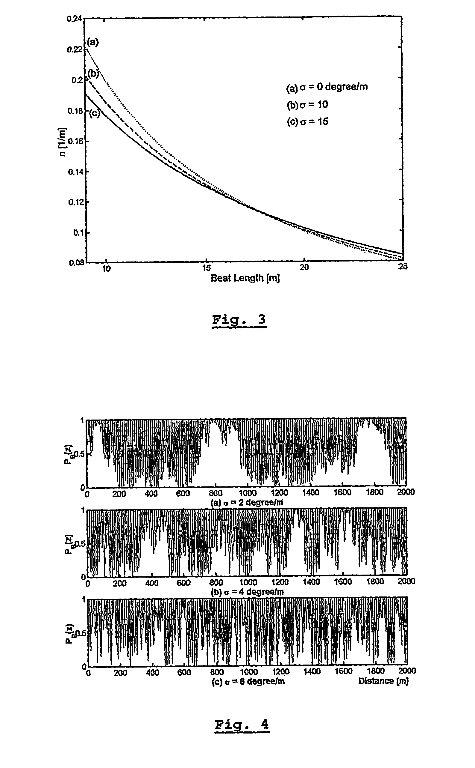
[0038] It is first shown how the polarisation mode dispersion from a POTDR signal can be determined in an accurate way (LB is not approximately determined anymore) by analysing the statistical properties of its extrema. Suppose first that σ falls within the range [0,15] degrees / m, which means that the coupling length is assumed to be larger than 12.8 m. This σ interval has been chosen such that it corresponds to the values measured on real fibres.

[0039] From a POTDR signal, the fibre length L, ξ and the number of maxima per unit of length, nm, are easily measurable. After measuring nm, it is possible to determine a first interval [LBlow1,LBup1]

for the beat length of the fibre under test so that: LB∈[LBlow1,LBup1]

LBlow1 and LBup1 are determined by the intersections of the curves n(LB, σ) corresponding to σ=0 and σ=15 degrees / m with the straight line n=nm as shown on FIG. 6.

[0040] When the first beat length interval is determined, the curves ξ(σ,LB) can be used to define an inte...


PUM


Abstract

A method for characterizing an optical link by its beat length, coupling length and polarization mode dispersion is disclosed. A pulsed signal is sent along said optical fiber link and the backscattered signal (being a POTDR signal) is measured after passing through a polarizer. The length of said optical fiber, the average power difference between two successive minima of said backscattered signal and the number of maxima per unit length are derived. In an iterative way a beat length interval and an interval for the polarization mode coupling parameter are determined until the length of said intervals is below a predetermined value, yielding a value for the beat length and the coupling length, and the polarization mode dispersion is calculated.

Description

FIELD OF THE INVENTION [0001] The present invention is related to a method for characterising an optical fibre link by analysis of a Rayleigh backscatter signal, from which the spatial distribution of the beat length, the coupling length and the PMD (Polarization Mode Dispersion) along the link can be determined. STATE OF THE ART [0002] The use of dispersion-shifted and dispersion compensating fibres has minimised the effect of chromatic dispersion on the bandwidth of an optical link. Polarisation mode dispersion (PMD) has therefore become the most serious limiting factor in high-speed optical communication systems. There exist several measurement techniques of PMD, but they only allow for measuring the global value and do not give information about the distribution of PMD along the fibre length. Measuring the spatial distribution of PMD is, however, important. Such a measurement would indeed allow to locate the bad trunks in an optical link, causing high PMD value. This can be esse...

Claims


Application Information

Patent Timeline
Patent Type & Authority Applications(United States)
IPC IPC(8): G02B6/00H04B10/071H04B10/2569
CPCG01M11/3181H04B10/2569H04B10/071
Inventor WUILPART, MARC
Owner FACULTE POLYTECHN DE MONS
Why Eureka
Try Eureka