Lever type connector

Active Publication Date: 2007-08-30
YAZAKI CORP +1
View PDF10 Cites 8 Cited by
  • Summary
  • Abstract
  • Description
  • Claims
  • Application Information

AI Technical Summary

Benefits of technology

[0023] According to the above construction, the claw portion can prevent the lever from separating from the supporting shaft. Further, since the lever is stably supported both by the claw portion and by the eng

Problems solved by technology

If this stress is considerably large, the

Method used


Image

  • Lever type connector
  • Lever type connector
  • Lever type connector

Examples


Embodiment Construction

[0034] An embodiment of the present invention will be explained below with reference to the drawings.

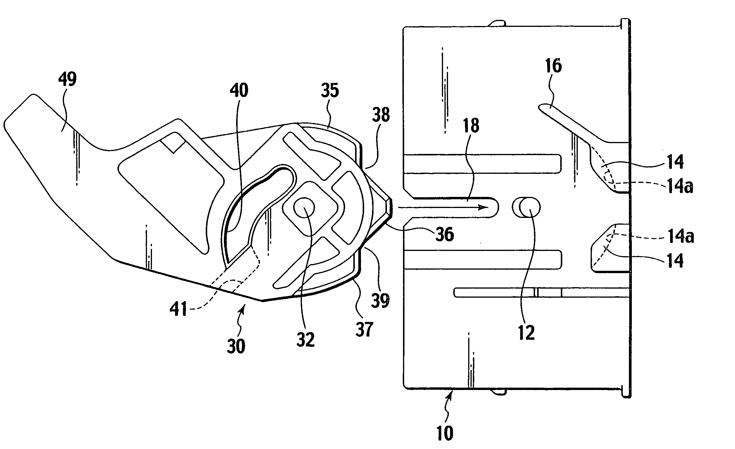
[0035] The lever type connector includes a first connector housing and a second connector housing configured to be connected to the first connector housing. FIGS. 1 to 4 show only a configuration of the first connector housing 10 and a lever 30 to clarify the present invention. The first connector housing has a terminal cavity (not shown) and a terminal (not shown) accommodated in the terminal cavity.

[0036] The lever 30, formed with a square U-shaped cross section, is fitted on an outer wall of the first connector housing 10. A hole 32 and a cam groove 40 are provided in a base portion of the lever 30. Further, a handle 49 is provided at an end of the lever 49.

[0037] The cam groove 40 is formed around the hole 32 in a predetermined angle range with respect to the hole 32. From a groove entrance 41 to an end of the cam groove, the cam groove 40 is curvilinearly formed so that the e...


PUM


Abstract

A lever type connector is provided with a lever assisting in fitting or detaching first and second connector housings thereof. A lever is fitted to the first connector housing. A plurality of projecting parts is provided in a circumference of the lever. A plurality of receiving parts is provided in the first connector housing to slidably engage with the projecting part Engagement between the projecting and receiving parts prevents the lever from deformation and warpage in a rotating operation of the lever for the connecting operation. The projecting parts and the receiving parts are configured so that the projecting parts and the receiving parts are engaged only when the lever is positioned so that the fitting force is large in the rotating operation, and the projecting parts and the receiving parts are not engaged when the lever is positioned in another state in which the fitting force is small.

Description

CROSS REFERENCE TO RELATED APPLICATION [0001] This application claims benefit of priority under 35 USC 119 based on Japanese Patent Application P2006-025918 filed Feb. 2, 2006, the entire contents of which are incorporated by reference herein. BACKGROUND OF THE INVENTION [0002] 1. Field of the Invention [0003] The present invention relates to a lever type connector capable of fitting or detaching one connector housing into or out of another connector housing, using a small force by a rotating operation of a lever. [0004] 2. Description of the Related Art [0005] In connectors like a multi-pin connector requiring large fitting or attachment force, a lever type connector provided with a lever is conventionally used so that the lever assists the attachment force. The lever type connector comprises a first connector housing (e.g. male connector housing); a lever rotatably provided in the first connector housing, the lever having a cam groove thereon; and a second connector (e.g. female c...

Claims


Application Information

Patent Timeline
IPC IPC(8): H01R13/62
CPCH01R13/62955H01R13/62938
Inventor SASAKI, YASUHIROYAMAMOTO, SHOJIYONEDA, TAKAHIROSAWADA, RYOYOSHIMURA, KEN
Owner YAZAKI CORP
Why Eureka
Try Eureka