Systems and methods for delivering a medical implant

a medical implant and system technology, applied in the field of systems and methods for delivering medical implants, can solve the problems of cardiac arrest, adverse reactions to anesthesia medications, bleeding, stroke,

Inactive Publication Date: 2007-08-30
BOSTON SCI SCIMED INC
View PDF99 Cites 609 Cited by
  • Summary
  • Abstract
  • Description
  • Claims
  • Application Information

AI Technical Summary

Benefits of technology

[0033] In some embodiments preventing the implant from being released includes capturing at least a portion of the medical implant in a space between the finger element and the actuatable element.

Problems solved by technology

Valve replacement surgery is a highly invasive operation with significant concomitant risk.
Risks include bleeding, infection, stroke, heart attack, arrhythmia, renal failure, adverse reactions to the anesthesia medications, as well as sudden death.
Valve anchors comprising standard self-expanding stent systems are expected to have very poor accuracy in deployment, however.
The stent may jump to another position once released, making it impossible to know where the ends of the stent will be after release with respect to the native valve, the coronary ostia and the mitral valve.
Due to the expected jumping action of some self-expanding anchors, and because the replacement valve may not be fully functional before final deployment, visualization of valve function and position prior to final and irreversible deployment may not be possible with these systems.
Another expected drawback of prior art self-expanding replacement heart valve systems is their relative lack of radial strength.
Expandable stent designs suitable for endovascular delivery for other purposes may not have sufficient radial strength to serve as replacement heart valve anchors.
However, when the stent has a valve fastened inside it, and that valve must reside within the heart, as is the case in aortic valve replacement, the anchoring of the stent to vessel walls takes significantly more radial force, especially during diastole.
Moreover, a self-expanding stent without sufficient radial force will end up dilating and contracting with each heartbeat, thereby distorting the valve, affecting its function and possibly causing it to migrate and dislodge completely.
Simply increasing strut thickness of the self-expanding stent is not a good solution as it increases profile and / or a risk of plastic deformation of the self-expanding stent.

Method used


Image

  • Systems and methods for delivering a medical implant
  • Systems and methods for delivering a medical implant
  • Systems and methods for delivering a medical implant

Examples


Embodiment Construction

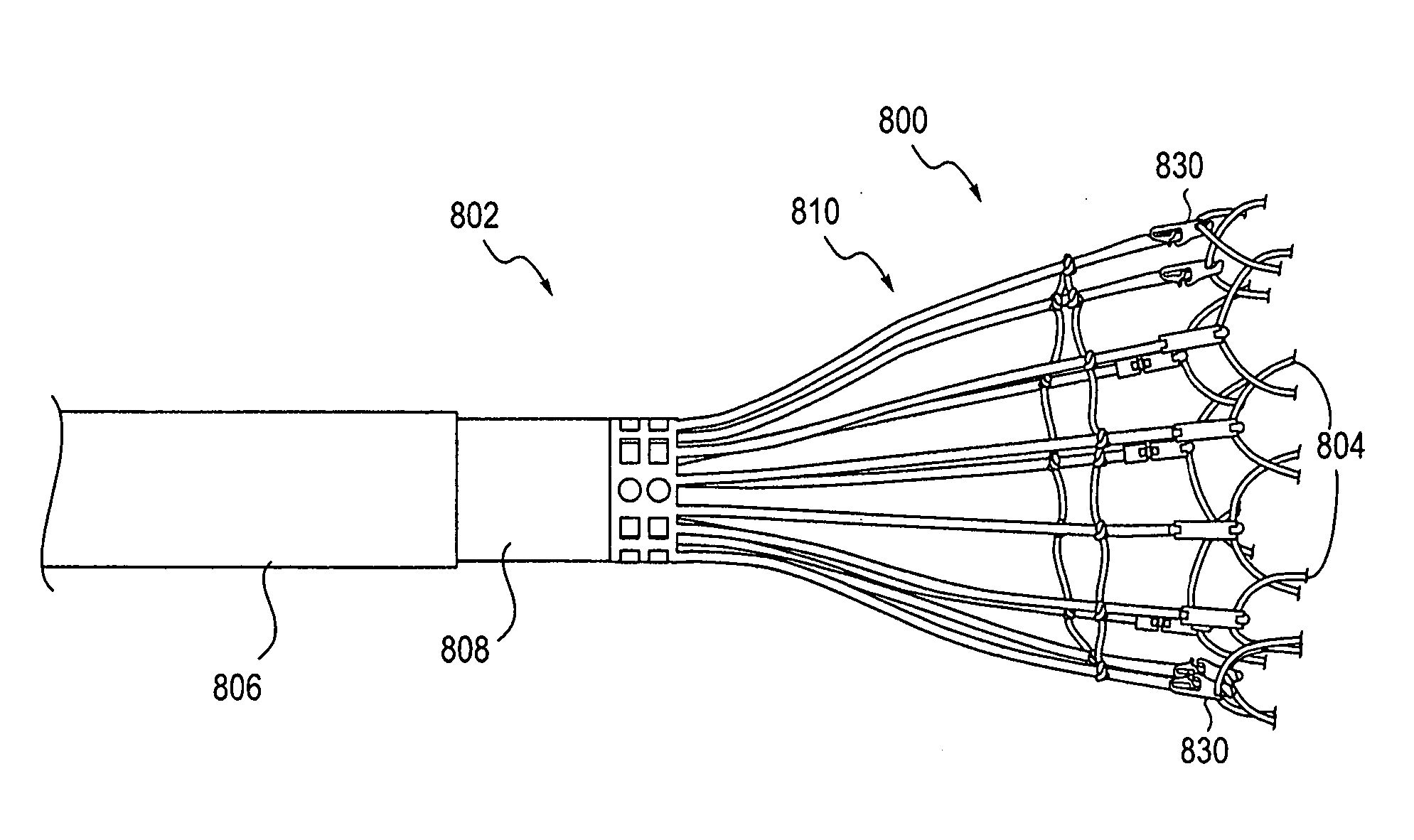
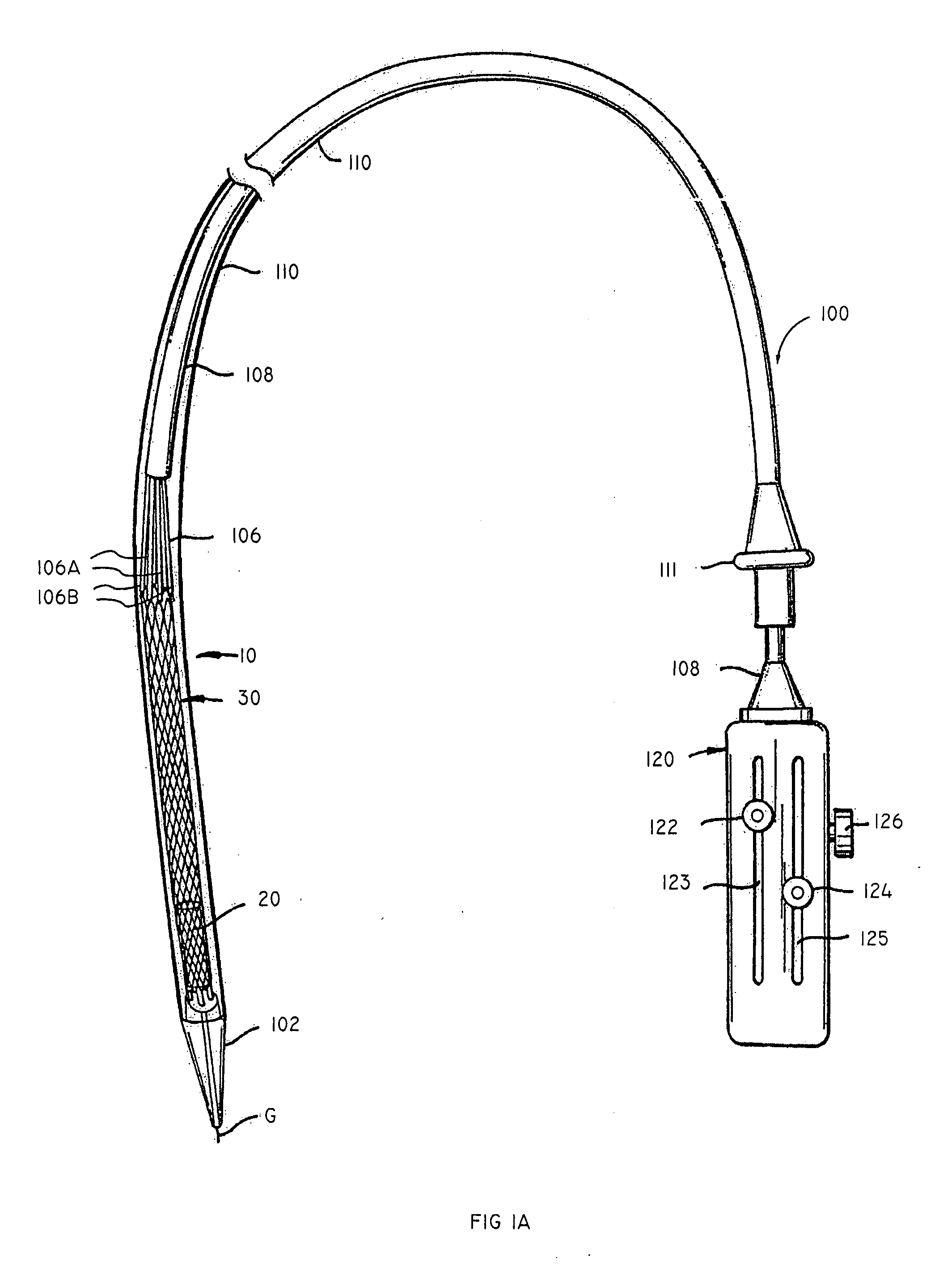
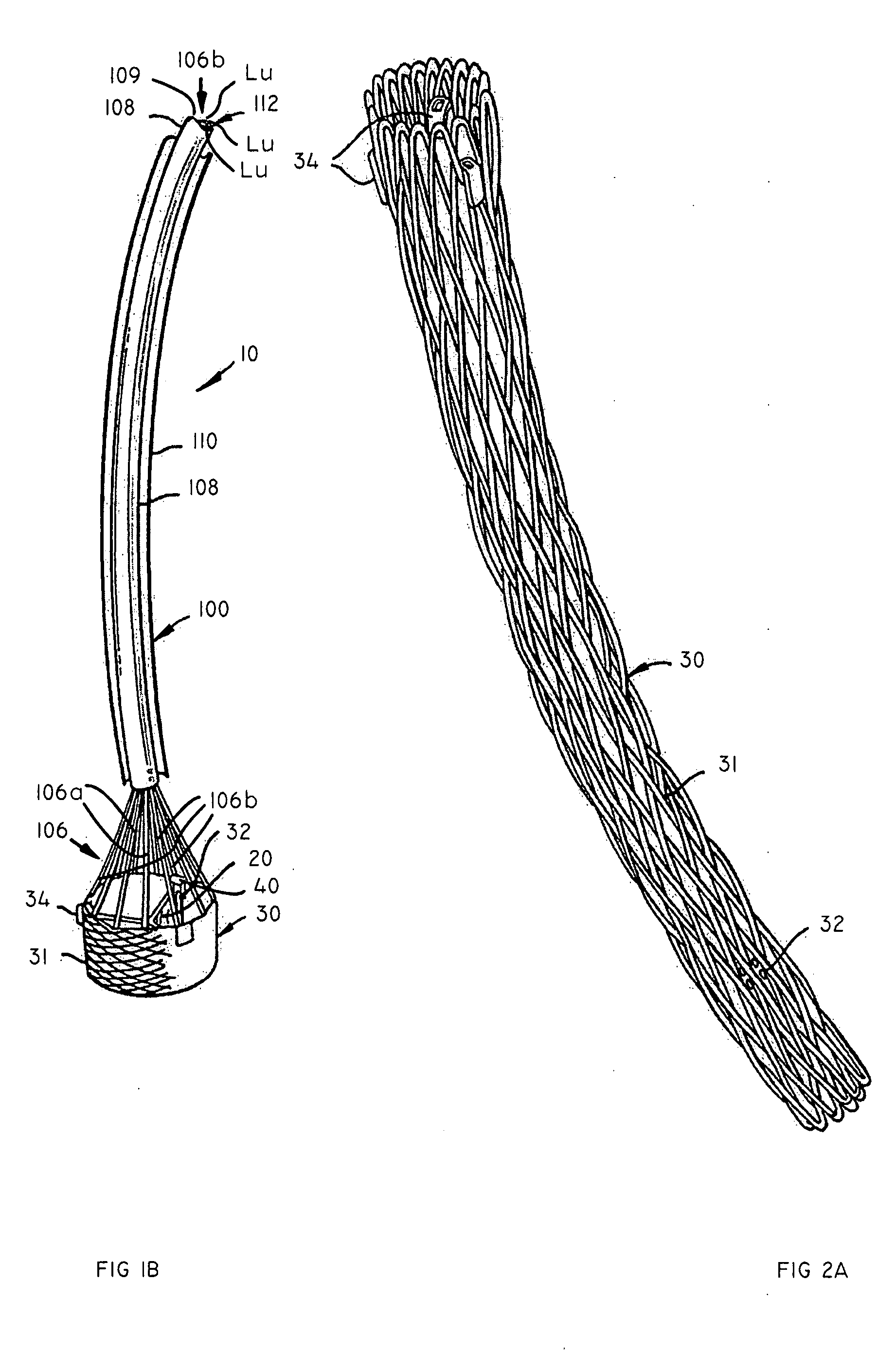
[0114] The present invention relates to apparatus and methods for endovascularly delivering and deploying a prosthesis, e.g., an aortic prosthesis, within and / or across a patient's native heart valve, referred to hereinafter as replacing the patient's heart valve. A delivery system and / or deployment tool is provided including a sheath assembly and a guidewire for placing the prosthetic apparatus endovascularly within the patient and a user control allowing manipulation of the prosthetic apparatus from external to the patient through the application of a non-hydraulically expanding or non-pneumatically expanding force on the anchor. A hydraulically or pneumatically expanding force would be, for example, a force applied to the anchor by a balloon expanded within the anchor. In certain embodiments, the application of a non-hydraulically expanding or non-pneumatically expanding force could include the use of a hydraulic component transmitting a proximally or distally directed force on a...


PUM


Abstract

The present invention relates to apparatus and methods for endovascularly delivering and releasing a prosthesis, e.g., an aortic prosthesis, within and/or across a patient's native heart valve, referred to hereinafter as replacing the patient's heart valve. In some embodiments the delivery system comprises a plurality of first actuatable element adapted to engage a plurality of second elements in a first configuration to capture the implant within the delivery system, and wherein the plurality of first actuatable element are adapted to engage the plurality of second elements in a second configuration and to release the implant from the delivery system.

Description

CROSS REFERENCE TO RELATED APPLICATIONS [0001] This application is a continuation-in-part of U.S. patent application Ser. No. 10 / 982,388, filed Nov. 5, 2004, which is a continuation-in-part application of U.S. patent application Ser. No. 10 / 746,120, filed Dec. 23, 2003, which applications are hereby incorporated by reference in their entirety. This application also claims the benefit of U.S. Provisional Application No. 60 / 743,288, filed Feb. 14, 2006, which application is hereby incorporated by reference in its entirety.INCORPORATION BY REFERENCE [0002] All publications and patent applications mentioned in this specification are herein incorporated by reference to the same extent as if each individual publication or patent application was specifically and individually indicated to be incorporated by reference. BACKGROUND OF THE INVENTION [0003] Heart valve surgery is used to repair or replace diseased heart valves. Valve surgery is an open-heart procedure conducted under general ane...

Claims


Application Information

Patent Timeline
Patent Type & Authority Applications(United States)
IPC IPC(8): A61F2/24A61F2/90
CPCA61B17/0644A61F2230/008A61B17/221A61B2017/22035A61B2017/2215A61F2/2409A61F2/2418A61F2/2433A61F2/2436A61F2/2439A61F2/90A61F2220/0008A61F2220/0016A61F2220/005A61F2220/0058A61F2230/005A61F2230/0078A61B17/068A61F2002/9534A61F2220/0025A61F2250/001A61F2/2427
Inventor SALAHIEH, AMRVALENCIA, HANS F.BRANDT, BRIAN D.ARGENTO, CLAUDIOHAUG, ULRICH R.DUERI, JEAN-PIERREHILDEBRAND, DANIELMOREJOHN, DWIGHT P.SAUL, TOM
Owner BOSTON SCI SCIMED INC
Why Eureka
Try Eureka