Combustion air vent control for furnaces

Inactive Publication Date: 2007-09-06
COWAN SCOTT DAVID
View PDF15 Cites 13 Cited by
  • Summary
  • Abstract
  • Description
  • Claims
  • Application Information

AI Technical Summary

Benefits of technology

[0007]The present invention provides an apparatus for controlling the vent used to supply combustion air to combustion furnaces. For a first embodiment of the invention, a furnace-controlled air valve is placed in the combustion air duct. Many types of valves can be used, including flapper valves, poppet valves, butterfly valves, ball valves, and inflatable balloon valves. When the furnace begins a heating cycle, the valve is opened. When the heating cycle ends, the valve is closed and remains closed until the beginning of the next heating cycle. A solenoid or electric motor may be used to control a flapper valve, a butterfly valve and a ball valve. When an electric motor is used, position sensors or timed pulses can be used to ensure that the valve is in the proper position at the beginning of each cycle. An inflatable balloon valve can be controlled with an air pump that inflates the balloon through a one-way valve so that leakage through the pump will not deflate the balloon. Air pump operation can be timed or it can be shut off with a pressure sensor. Deflation of the balloon during heating cycles can be accomplished by sending a pulse of sufficient length to a solenoid-controlled valve which will permit the pressured air within the balloon to escape.
[0008]A second embodiment of the invention employs a positive-displacement air pump, which is placed in the combustion air duct and prevents most back-flow leakage of air. Many types of positive-displacement pumps are

Problems solved by technology

Unfortunately, high-efficiency furnaces are not installed in the majority of new homes.
In an airtight structure, a furnace will deplete the available oxygen and begin to produce carbon monoxide as combustion becomes increasingly incomplete.
Because mechanical rooms are rarely well sealed from the rest of the house, combustion air vents can be a significant source of heat loss.
Another problem related to cold air entering the combustion air vent is that the dw

Method used


Image

  • Combustion air vent control for furnaces
  • Combustion air vent control for furnaces
  • Combustion air vent control for furnaces

Examples


Embodiment Construction

[0024]The invention will now be described in detail with reference to the attached drawing figures.

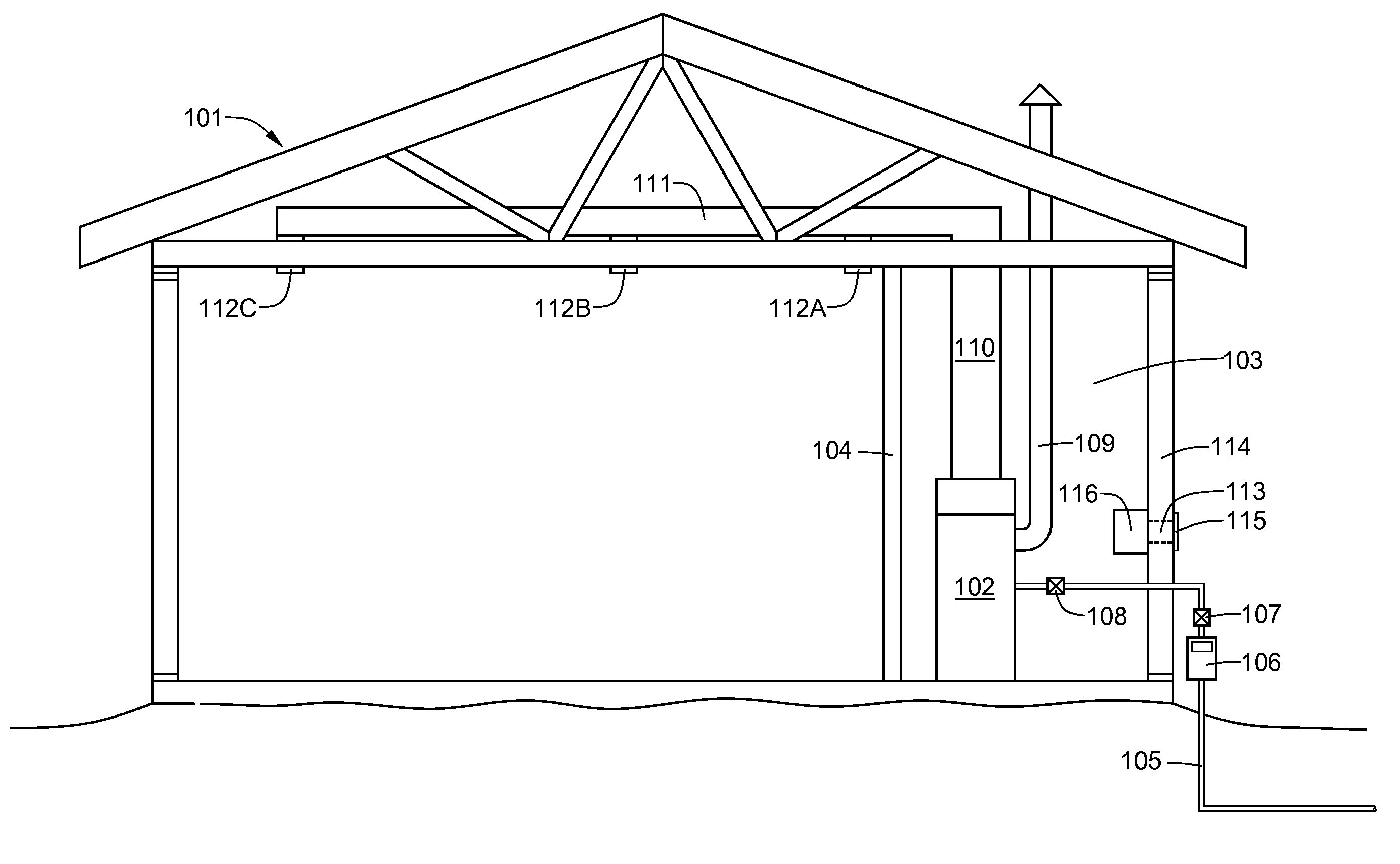
[0025]Referring now to FIG. 1, a cutaway view of a home 101 is shown, in which a combustion natural gas furnace 102 has been installed in the mechanical room 103. A wall 104 separates the mechanical room 103 from the rest of the house. A natural gas supply pipe 105 supplies natural gas to a meter 106. Natural gas is fed to the furnace 102 first through an exterior cut-off valve 107 and then through an interior cut-off valve 108 positioned near the furnace 102. An exhaust flue 109 transfers combustion products from the furnace 102 to outside the home 101. A vertical air duct 110 transports heated air from the furnace 102 to a horizontal air duct 111 in the ceiling, from which the heated air is expelled from various ceiling registers 112A, 112B, and 112C. A combustion air vent 113 provides combustion air from the exterior of the house to the mechanical room 103. The furnace 102 then pull...


PUM


Abstract

Various apparatus are disclosed for controlling the combustion air vent of fuel-fired furnaces. For a first embodiment of the invention, a furnace-controlled air valve is placed in the combustion air duct. When the furnace begins a heating cycle, the valve is opened. When the heating cycle ends, the valve is closed and remains closed until the beginning of the next heating cycle. For a second embodiment of the invention, a positive-displacement air pump is placed in the combustion air duct. The air pump pumps air from the exterior into the mechanical room at a controlled rate during each heating cycle of the furnace. The air valve or the air pump is controlled directly or indirectly by the furnace thermostat.

Description

[0001]This application has a priority date based on the filing of Provisional Patent Application No. 60 / 765,821, titled COMBUSTION AIR VENT CONTROL FOR FURNACES, on Feb. 7, 2006.BACKGROUND OF THE INVENTION[0002]1. Field of the Invention[0003]This invention relates to combustion furnaces and, more particularly, to the control of combustion air intakes for combustion furnaces having a combustion chamber that is not directly connected to the combustion air intake.[0004]2. Description of the Prior Art[0005]High-efficiency gas furnaces (those having efficiency ratings greater than 90 percent) typically have both a combustion air intake and a low-temperature exhaust vent, both of which are coupled directly to the combustion chamber of the furnace. As the combustion chamber is sealed from the room in which the furnace is installed, there can be little leakage of cold outside air into the room. Unfortunately, high-efficiency furnaces are not installed in the majority of new homes. Typically...

Claims


Application Information

Patent Timeline
IPC IPC(8): F24C15/00F24C3/00
CPCF23L3/00F23L5/02F23N2035/08F23N3/042F23L13/02F23N2235/08
Inventor COWAN, SCOTT DAVID
Owner COWAN SCOTT DAVID
Why Eureka
Try Eureka