Passive analog thermal isolation structure

a passive analog and thermal isolation technology, applied in the direction of process and machine control, lighting and heating apparatus, instruments, etc., can solve the problems of thermal bimorph to deformation, and achieve the effect of reducing power consumption and reducing the complexity of control electronics required

Inactive Publication Date: 2007-09-06
HONEYWELL INT INC
View PDF15 Cites 20 Cited by
  • Summary
  • Abstract
  • Description
  • Claims
  • Application Information

AI Technical Summary

Benefits of technology

[0007] During use, the thermal bimorphs can be configured to deform and make contact with the cap wafer at different temperatures, forming a number of thermal shorts that transfer heat from the substrate wafer to the cap wafer. When attached to a microdevice such as MEMS device, the thermal isolation structure can be configured to maintain the attached device at a constant temperature and / or within a desired temperature range. In some applications, the thermal isolation structure can permit the microdevice to self-heat to a particular temperature without the use of active heating elements, reducing power consumption and decreasing the complexity of the control electronics required to operate the device.

Problems solved by technology

In this embodiment, when the substrate is heated, the double-ended thermal bimorph expands more than the substrate, resulting in an induced stress that causes the thermal bimorph to deform.

Method used


Image

  • Passive analog thermal isolation structure
  • Passive analog thermal isolation structure
  • Passive analog thermal isolation structure

Examples


Embodiment Construction

[0014] The following description should be read with reference to the drawings, in which like elements in different drawings are numbered in like fashion. The drawings, which are not necessarily to scale, depict selected embodiments and are not intended to limit the scope of the invention. Although examples of construction, dimensions, and materials are illustrated for the various elements, those skilled in the art will recognize that many of the examples provided have suitable alternatives that may be utilized.

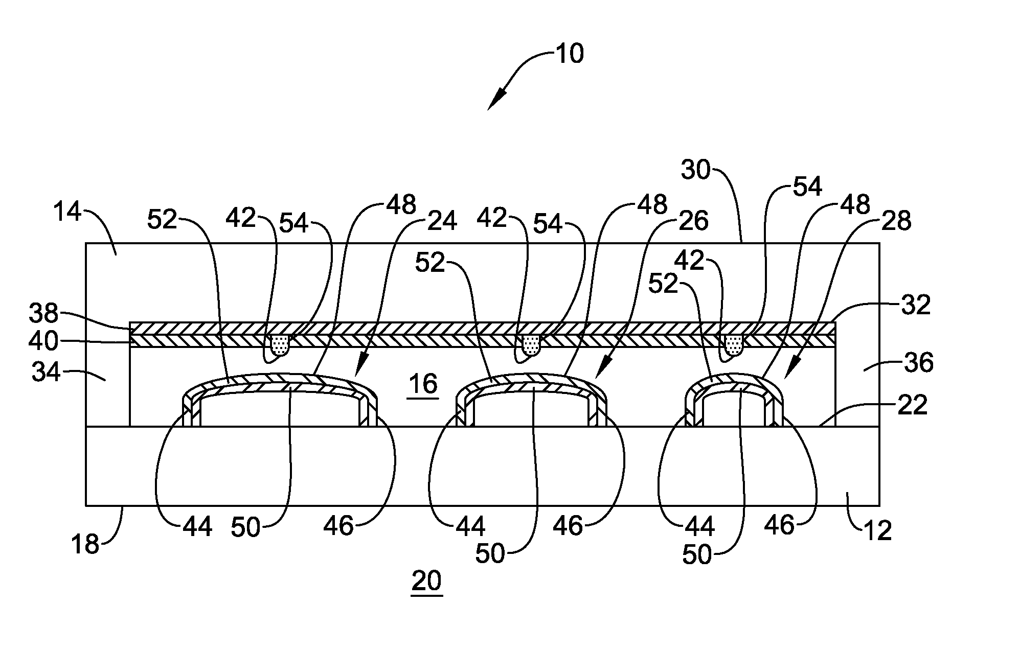
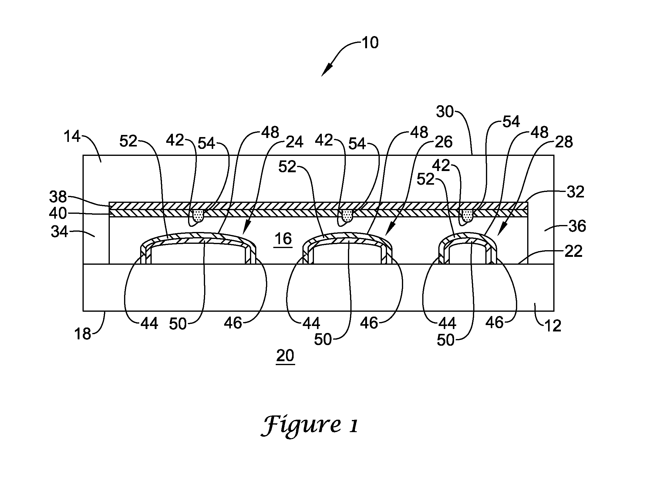
[0015]FIG. 1 is a schematic side cross-sectional view showing an illustrative passive analog thermal isolation structure 10 in accordance with an exemplary embodiment of the present invention. As shown in FIG. 1, the thermal isolation structure 10 can include a bottom substrate 12 and a top cap 14, which together define a sealed interior cavity 16 of the structure 10. The bottom substrate 12 can have a first side 18 that can be placed in intimate thermal contact with an exte...


PUM


Abstract

A thermal isolation structure for use in passively regulating the temperature of a microdevice is disclosed. The thermal isolation structure can include a substrate wafer and a cap wafer defining an interior cavity, and a number of double-ended or single-ended thermal bimorphs coupled to the substrate wafer and thermally actuatable between an initial position and a deformed position. The thermal bimorphs can be configured to deform and make contact with the cap wafer at different temperatures, creating various thermal shorts depending on the temperature of the substrate wafer. When attached to a microdevice such as a MEMS device, the thermal isolation structure can be configured to maintain the attached device at a constant temperature or within a particular temperature range.

Description

GOVERNMENT SUPPORT [0001] This invention was made with government support under DARPA contract number N66001-02-C-8019. The government may have certain rights in the invention.FIELD [0002] The present invention relates generally to the field of temperature control in microdevices. More specifically, the present invention pertains to passive analog thermal isolation structures for use with microdevices such as MEMS devices. BACKGROUND [0003] Microelectromechanical systems (MEMS) are becoming increasingly popular as an alternative to conventional electromechanical devices such as inertial sensors, switches, relays, actuators, optical lenses, and valves. In the fabrication of inertial sensors for use in navigational and communications systems, for example, many of the sensor components such as gyroscopes and accelerometers are now being fabricated on etched wafers using batch semiconductor fabrication techniques. Because these MEMS devices can be fabricated on a smaller scale and with ...

Claims


Application Information

Patent Timeline
Patent Type & Authority Applications(United States)
IPC IPC(8): H01L29/82
CPCB81B7/0087B81B2201/032F28F2270/00G05D23/024F28F13/00
Inventor YOUNGNER, DAN W.LUST, LISA M.
Owner HONEYWELL INT INC
Why Eureka
Try Eureka