Organic light-emitting diode display, organic light-emitting diode panel and driving device thereof

Inactive Publication Date: 2007-09-06
AU OPTRONICS CORP
View PDF7 Cites 11 Cited by
  • Summary
  • Abstract
  • Description
  • Claims
  • Application Information

AI Technical Summary

Benefits of technology

[0012]The present invention provides an OLED display, an OLED panel and a driving device, wherein the OLED display includes the OLED panel and the driving device and is suitable for adjusting the luminance of the sub-pixels to produce expected colors without changing the other components and the configuration thereof.
[0013]The driving circuit of the present invention is independent from the pixel circuit, so that the aperture ratio thereof is not affected and further different currents can be used to drive the pixel circuit.
[0023]Since the present invention adopts current mirrors to convert the data currents, thus, it is able to adjust the luminance of sub-pixels by controlling the ratios between the channel width and channel length of the driving transistors in the current mirrors, so that the luminance ratios among the red sub-pixel, the green red sub-pixel and the blue red sub-pixel meet the requirement to form white light and to achieve the full colorization goal of an OLED display. Note that the scheme that a plurality of sub-pixels is driven by a data current makes the driving method simpler as well.

Problems solved by technology

Referring to FIG. 1, it can be seen that for driving currents with the same amount, the luminance produced by red, green and blue OLED pixels is different from each other, However, such a result does not meet the real requirement of an OLED display.
Nevertheless, such luminance ratios may not meet the requirement of an OLED display where the luminance ratios among the red OLED, the green OLED and the blue OLED must comply with the required proportion to form white light, so to achieve full colorization for an OLED display.
Hence, a scheme using the same data currents corresponding to a same gray-level to drive the red sub-pixel, the green sub-pixel and the blue sub-pixel having different characteristics is not a proper design, since the luminance ratios thereof do not comply with the required proportion to form white light.
Note that the conventional OLED panel shown in FIG. 2, wherein three different sets of data currents corresponding to the gray-levels are required to individually drive the three sub-pixels, brings a quite complicate driving method to be implemented.
However, such a conventional design would affect the aperture ratio of a display and fail to optimize the aperture ratio.

Method used


Image

  • Organic light-emitting diode display, organic light-emitting diode panel and driving device thereof
  • Organic light-emitting diode display, organic light-emitting diode panel and driving device thereof
  • Organic light-emitting diode display, organic light-emitting diode panel and driving device thereof

Examples


first embodiment

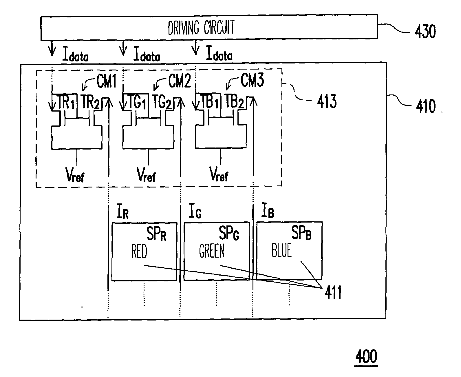
[0032]FIG. 4 is a diagram of an OLED display structure according to the present invention. Referring to FIG. 4, the OLED display 400 provided by the embodiment includes an OLED panel 410 and a driving circuit 430.

[0033]The OLED panel 410 provided by the present invention has a plurality of display pixels 411 and a driving device 413 disposed in the OLED panel 410. Wherein, every display pixel 411 includes a plurality of sub-pixels, for example, a sub-pixel SPR, a sub-pixel SPG and a sub-pixel SPB. In the embodiment, the sub-pixels SPR, SPG and SPB correspond, but not limited to by the present invention, to red color, the green color and blue color.

[0034]The driving device 413 provided by the present invention includes a current mirror CM 1, a current mirror CM2 and a current mirror CM3 for correspondingly receiving one of the data currents Idata come from the driving circuit 430 and creating a driving current IR, a driving current IG and a driving current IB sent to the correspondin...

second embodiment

[0047]FIG. 5 is a diagram of an OLED display structure according to the present invention (where the data line is directly coupled to a driving current). Referring to FIG. 5, the OLED display 500 of the embodiment includes an OLED panel 510 and a driving circuit 430, wherein the OLED panel 510 has a plurality of display pixels 411 and a driving device 413. In the same way, the display pixel 411 includes a plurality of sub-pixels SPR, SPG and SPB.

[0048]Similar to FIG. 4, the driving device 413 includes a current mirror CM1, a current mirror CM2 and a current mirror CM3 for correspondingly receiving one of the data currents Idata come from the driving circuit 430 and creating a driving current IR, a driving current IG and a driving current IB sent to the corresponding sub-pixels SPR, SPG and SPB, respectively. The current mirror CM1 includes a transistor TR1, and a transistor TR2, the current mirror CM2 includes a transistor TG1 and a transistor TG2 and the current mirror CM3 includes...

third embodiment

[0050]FIG. 6 is a diagram of an OLED display structure according to the present invention. Referring to FIG. 6, an OLED display 600 provided by the present embodiment includes an OLED panel 610 and a driving circuit 630. Similarly, the OLED panel 610 includes a plurality of display pixels 611 and a driving device 613, too. In particular, the display pixels 611 in the embodiment includes a plurality of sub-pixels SPR, SPG, SPB and SPW respectively corresponding to red light, green light, blue light and white light.

[0051]For the most part, the structure of the driving device 613 is similar to the above-described first embodiment and second embodiment. In the embodiment, however, each of the display pixels includes four sub-pixels. Therefore, an extra current mirror CM4 is required in the driving device 613 for receiving a corresponding data current Idata and creating a driving current IW sent to the sub-pixel SPW.

[0052]The current mirror CM4 includes a transistor TW1 and a transistor ...


PUM


Abstract

An OLED display, an OLED panel and a driving device are disclosed. Wherein, the OLED display includes the OLED and the driving device. The OLED panel has a plurality of display pixels, every display pixel includes a plurality of sub-pixels, and each of the sub-pixels respectively corresponds to a different color. The driving device includes a plurality of current mirrors for correspondingly receiving one of a plurality of data currents and for generating driving currents sent to the corresponding sub-pixels, respectively. Each the current mirror includes a plurality of transistors and generates a different driving current to drive the corresponding sub-pixels according to the ratios between the channel widths and channel lengths of the transistors in the current mirror.

Description

CROSS-REFERENCE TO RELATED APPLICATION[0001]This application claims the priority benefit of Taiwan application serial no. 95107165, filed on Mar. 3, 2006. All disclosure of the Taiwan application is incorporated herein by reference.BACKGROUND OF THE INVENTION[0002]1. Field of Invention[0003]The present invention relates to a driving device, and particularly to a driving device of an organic light-emitting diode panel (OLED panel).[0004]2. Description of the Related Art[0005]FIG. 1 is a characteristic curve chart of luminance vs. current for different color organic light-emitting diodes (OLEDs). Referring to FIG. 1, it can be seen that for driving currents with the same amount, the luminance produced by red, green and blue OLED pixels is different from each other, However, such a result does not meet the real requirement of an OLED display. In fact, different OLED displays require different luminance ratios among the red OLED, the green OLED and the blue OLED. Therefore, how to make ...

Claims


Application Information

Patent Timeline
IPC IPC(8): G09G3/30
CPCG09G3/2003G09G2320/0242G09G3/3241
Inventor CHEN, PEI-MING
Owner AU OPTRONICS CORP
Why Eureka
Try Eureka