
Fluidically damped printhead

a printhead and flue technology, applied in the direction of printing, inking apparatus, etc., can solve the problems of high print speed, high print speed, and high cost of ink supply, and achieve the effect of reducing the likelihood of trace cracking and risking localized points of high stress on the traces

Active Publication Date: 2007-09-06
MEMJET TECH LTD +1
View PDF44 Cites 25 Cited by
  • Summary
  • Abstract
  • Description
  • Claims
  • Application Information

AI Technical Summary

Benefits of technology

[0017]Damping pressure pulses using gas compression can be achieved with small volumes of gas. This preserves a compact design while avoiding any nozzle flooding from transient spikes in the ink pressure.
[0103]Optionally, the support structure has a curved surface to support the bent section of the flex PCB. The curved surface reduces the likelihood of trace cracking by holding the flex PCB at a set radius rather than allowing the flex to follow an irregular curve in the bent section, and thereby risking localized points of high stress on the traces.

Problems solved by technology

Printing at these speeds consumes ink quickly and this gives rise to problems with supplying the printhead with enough ink.
Not only are the flow rates higher but distributing the ink along the entire length of a pagewidth printhead is more complex than feeding ink to a relatively small reciprocating printhead.
The high print speeds require a relatively large ink supply flow rate.
Abruptly ending a print job, or simply at the end of a printed page, means that this relatively high volume of ink that is flowing relatively quickly must also come to an immediate stop.
However, suddenly arresting the ink momentum gives rise to a shock wave in the ink line.
If the nozzles flood, ink may not eject and artifacts appear in the printing.
This can result in nozzle flooding, or conversely nozzle deprime because of the sudden pressure drop after the spike, if the Laplace pressure is exceeded.

Method used


Image

  • Fluidically damped printhead
  • Fluidically damped printhead
  • Fluidically damped printhead

Examples


Embodiment Construction

Overview

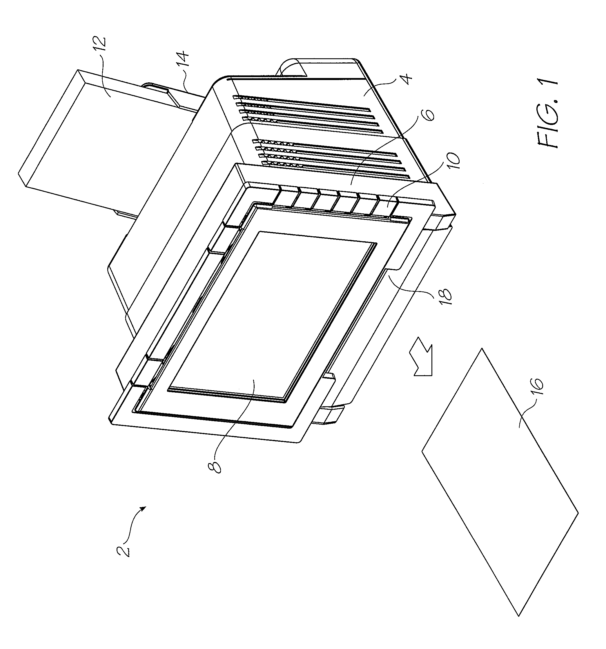
[0141]FIG. 1 shows a printer 2 embodying the present invention. The main body 4 of the printer supports a media feed tray 14 at the back and a pivoting face 6 at the front. FIG. 1 shows the pivoting face 6 closed such that the display screen 8 is its upright viewing position. Control buttons 10 extend from the sides of the screen 8 for convenient operator input while viewing the screen. To print, a single sheet is drawn from the media stack 12 in the feed tray 14 and fed past the printhead (concealed within the printer). The printed sheet 16 is delivered through the printed media outlet slot 18.

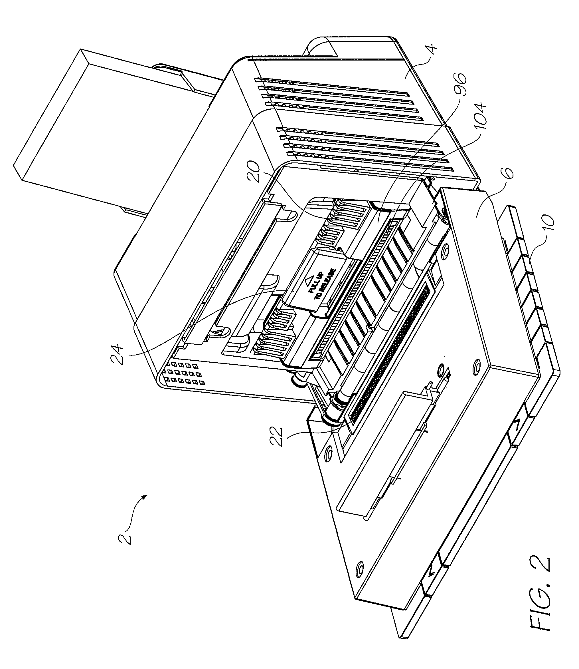
[0142]FIG. 2 shows the pivoting front face 6 open to reveal the interior of the printer 2. Opening the front face of the printer exposes the printhead cartridge 96 installed within. The printhead cartridge 96 is secured in position by the cartridge engagement cams 20 that push it down to ensure that the ink coupling (described later) is fully engaged and the printhead ICs (described l...


PUM


Abstract

A printhead for an inkjet printer that has a printhead integrated circuit (68) with nozzles for ejecting ink, and a support structure (64, 176, 108) for supporting the printhead IC. The support structure has ink conduits (182) for supplying the nozzles with ink and a fluidic damper 200 containing gas for compression by pressure pulses in the ink within the ink conduits to dissipate the pressure pulse. Damping pressure pulses using gas compression can be achieved with small volumes of gas. This preserves a compact design while avoiding any nozzle flooding from transient spikes in the ink pressure.

Description

CROSS REFERENCE TO RELATED APPLICATIONS[0001]This application is a Continuation-in-part of 11 / 677049, filed Feb. 21, 2007, all of which is incorporated herein by reference.CO-PENDING APPLICATIONS[0002]The following applications have been filed by the Applicant simultaneously with the present application:[0003]RRE002US RRE003US RRE004US RRE005US RRE006US[0004]RRE007US RRE008US RRE009US RRE010US[0005]The disclosures of these co-pending applications are incorporated herein by reference. The above applications have been identified by their filing docket number, which will be substituted with the corresponding application number, once assigned.CROSS REFERENCES[0006]The following patents or patent applications filed by the applicant or assignee of the present invention are hereby incorporated by cross-reference.64050556628430713618610 / 920372714568971300757081974717705510 / 9192437161715715463271582587148993707568411 / 63552611 / 65054511 / 65324111 / 65324010 / 503924710843769151406999206713619870921...

Claims


Application Information

Patent Timeline
Patent Type & Authority Applications(United States)
IPC IPC(8): B41J2/04
CPCB41J2/14B41J2/155B41J2/1707B41J2/175B41J2202/20B41J2002/14419B41J2002/14491B41J2202/19B41J2/17596B41J2/17556
Inventor BROWN, BRIAN ROBERTBERRY, NORMAN MICHEALJACKSON, GARRY RAYMONDSHARP, PAUL TIMOTHYMORGAN, JOHN DOUGLAS PETERSILVERBROOK, KIANAKAZAWA, AKIRAHUDSON, MICHAEL JOHNHIBBARD, CHRISTOPHERMALLINSON, SAMUEL GEORGEREICHL, PAUL JUSTIN
Owner MEMJET TECH LTD
Features
  • Generate Ideas
  • Intellectual Property
  • Life Sciences
  • Materials
  • Tech Scout
  • Unparalleled Data Quality
  • Higher Quality Content
  • 60% Fewer Hallucinations
Learn More