Adjustable catheter tip

a catheter tip and adjustable technology, applied in the field of delivery systems, can solve the problems of difficult challenges for catheters within tortuous vessel structures, such as coronary arteries and arteries supplying the brain, and achieve the effect of improving the safety and comfort of patients

Inactive Publication Date: 2007-09-06
BOSTON SCI SCIMED INC
View PDF21 Cites 129 Cited by
  • Summary
  • Abstract
  • Description
  • Claims
  • Application Information

AI Technical Summary

Benefits of technology

[0010] In at least one embodiment, the invention is directed to a catheter tip with a shaft comprising an outer surface section, an inner surface section and at least one section of electroactive polymer (EAP). The EAP has an actuated state and a non-actuated state. The section of EAP can be any desired width, length and depth depending upon the effect desired when the EAP is in an actuated state. In at least one embodiment, the at least one section of EAP is positioned within the inner surface section. In one embodiment, the at least one section of EAP, positioned within the inner surface section, volumetrically expands when in an actuated state. In another embodiment, the at least one section of EAP is positioned within the inner surface section and volumetrically contracts when in an actuated state.

Problems solved by technology

The guidance of a catheter within a tortuous vessel structure, such as a coronary artery and the arteries supplying the brain, often present difficult challenges.

Method used


Image

  • Adjustable catheter tip
  • Adjustable catheter tip
  • Adjustable catheter tip

Examples


Embodiment Construction

[0056] While this invention may be embodied in many different forms, there are described in detail herein specific embodiments of the invention. This description is an exemplification of the principles of the invention and is not intended to limit the invention to the particular embodiments illustrated.

[0057] For the purposes of this disclosure, like reference numerals in the figures shall refer to like features unless otherwise indicated.

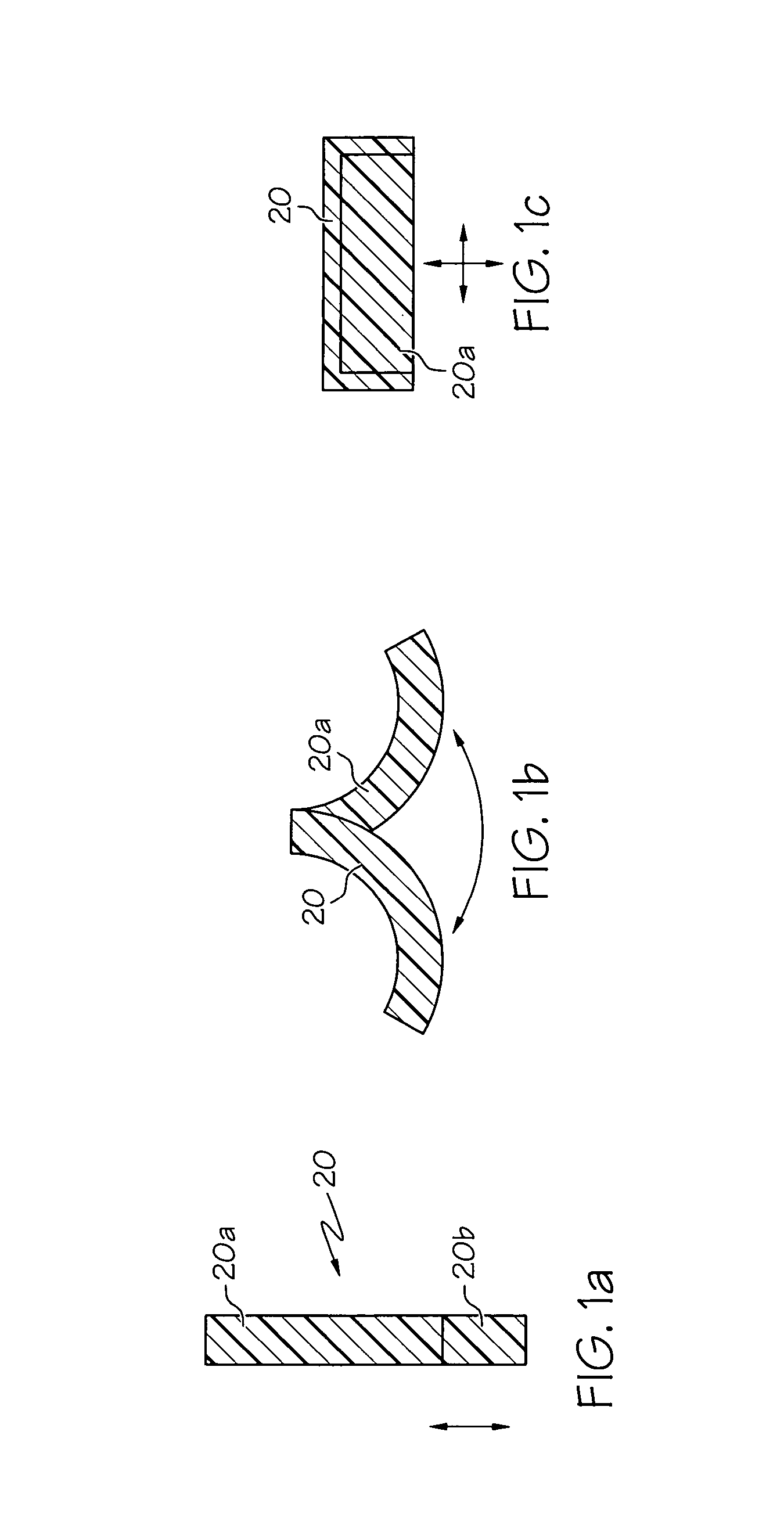
[0058] EAP has been discovered to be useful in a number of applications related to the design of catheter tips. EAPs have the ability to change shape upon actuation or deactuation.

[0059]FIGS. 1a-c depict different ways EAP 20 can behave when actuated. FIG. 1a depicts how EAP 20 can increase or decrease its linear length. When EAP 20a is actuated, the linear length increases, the additional length denoted by portion 20b. The EAP may also be configured so that it decreases in length upon actuation. FIG. 1b shows how EAP 20 can bend when actuated w...


PUM


Abstract

A catheter tip has an outer surface section, an inner surface section, a spatial configuration and at least one segment of electroactive polymer. The inner surface section defines a guide wire lumen. The electroactive polymer has an actuated state and a non-actuated state. In an actuated state, the electroactive polymer alters the spatial configuration of the catheter tip.

Description

CROSS-REFERENCE TO RELATED APPLICATIONS [0001] Not Applicable STATEMENT REGARDING FEDERALLY SPONSORED RESEARCH [0002] Not Applicable FIELD OF THE INVENTION [0003] In some embodiments, this invention relates to delivery systems, such as catheter systems of all types, which are utilized in the delivery of implantable devices. Specifically, this invention relates to catheter tips. BACKGROUND OF THE INVENTION [0004] Catheters are thin flexible tubes which are introduced into a vein or artery and guided to selected sites in the vascular system. Angiographic catheters are employed to inject contrast media into a vessel to visualize the shape, state, topography, functionality and other characteristics of the vessel for the purpose of diagnosing anatomic abnormalities of an organ and its conduits. Such catheters are used, for instance, to diagnose diseases of the heart and the circulatory system. [0005] The guidance of a catheter within a tortuous vessel structure, such as a coronary artery...

Claims


Application Information

Patent Timeline
Patent Type & Authority Applications(United States)
IPC IPC(8): A61M25/00
CPCA61B2017/00398A61B2017/00871A61M25/001A61M25/0069A61M2025/09125A61M25/10A61M2025/0024A61M2025/0058A61M2025/0063A61M25/0074
Inventor KORNKVEN VOLK, ANGELAJAGGER, KARL A.EIDENSCHINK, TRACEEOLSON, RICHARDBLIX, JOHNSUTERMEISTER, DEREKRASSAT, JAY
Owner BOSTON SCI SCIMED INC
Why Eureka
Try Eureka