Radiation image pickup apparatus

a technology of radio frequency pickup and image, which is applied in the direction of radio frequency controlled devices, television systems, instruments, etc., can solve the problems of insufficient, active system, large fpn, etc., and achieve the effect of preventing the generation of fixed pattern noise, and reducing the number of fpn

Inactive Publication Date: 2007-09-13
KONICA MINOLTA MEDICAL & GRAPHICS INC
View PDF4 Cites 23 Cited by
  • Summary
  • Abstract
  • Description
  • Claims
  • Application Information

AI Technical Summary

Benefits of technology

[0025] According to the present invention, the first detecting element for measuring the radiation amount is selected from the detecting element for conducting the radiation image pickup, and when the electric signal obtained by conducting the converting operation by the first detecting element, is held in the output circuit, it can be structured such that it is not necessary that the electric signal from the detecting element is amplified. Therefore, the element conducting the amplifying operation or circuit like as the source follower circuit is not necessary, and the generation of the fixed pattern noise can be prevented. Further, the photo timer function can be realized without separately providing a special output circuit, and the apparatus structure can be simplified. Further, because the output of the first detecting element can also be used as the image data, the deterioration of the resolution is not caused.

Problems solved by technology

This FPN has a tendency that it becomes large as the image pickup area becomes large, and is not adequate to the radiation image pickup apparatus in which the large area image pickup is necessary.
Further, there is a problem that the threshold voltage is sifted in TFT, and because the analogous characteristic is unstable, it is very difficult that the active system sensor in which the light having the broad image pickup area is the prime number, is realized by using TFT.

Method used


Image

  • Radiation image pickup apparatus
  • Radiation image pickup apparatus
  • Radiation image pickup apparatus

Examples


first embodiment

The First Embodiment

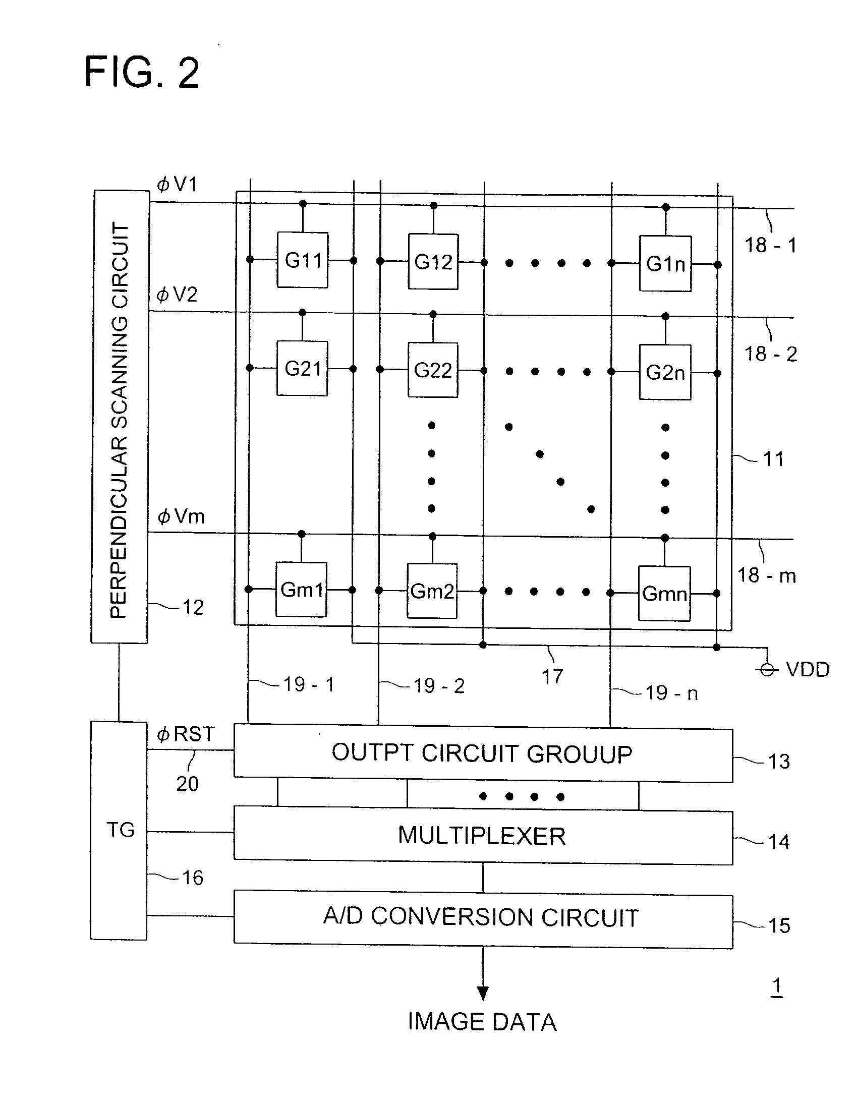
[0051] Referring to the drawings, the first embodiment of the present invention will be described. FIG. 2 is an outline block diagram showing the internal structure of FPD in the radiation image pickup apparatus of the present embodiment.

[0052] FPD1 is, as shown in FIG. 2, provide with: a sensor section 11 having the detecting elements G11-Gmn provided with the photo diode PD and the thin film transistor T arranged in a form of a matrix; a perpendicular scan circuit 12 for scanning in the perpendicular direction each of detecting elements G11-Gmn of the sensor section 11 at the time of the data output; output circuit group 13 for holding for each line in the matrix arrangement the electric signal outputted from each of detecting elements G11-Gmn of the sensor section 11; a multiplexer 14 for converting the electric signals held in the output circuit group 13 into the serial electric signal for each row; the A / D conversion circuit 15 for converting the electric s...

second embodiment

The Second Embodiment

[0103] Referring to the drawings, the second embodiment of the present invention will be described. FIG. 13 is an outline block diagram showing the internal structure of FPD in the radiation image pickup apparatus of the present embodiment. Hereupon, the structure of the detecting elements and output circuits provided in FPD shown in FIG. 13 is, in the same as the first embodiment, the structure in FIG. 3.

[0104] FPD1a in the radiation image pickup apparatus of the present embodiment provides, as shown in FIG. 13, a sensor section 11x providing m line n row detecting elements Gx11-Gxm, and sensor section 11y providing m line n row detecting elements Gy11-Gymn, and output circuit group 13x by output circuits 13x-1-13x-n holding for each line the electric signal outputted from each detecting element Gx11-Gxmn of the sensor section 11, and output circuit group 13y by the output circuit 13-y-13y-n holding for each line the electric signal outputted from each detecti...

third embodiment

The Third Embodiment

[0113] Referring to the drawings, the third embodiment of the present invention will be described. FIG. 15 is a view showing The relationship between the line in which the detecting element is aligned for the x-ray amount measurement in the radiation image pick-up apparatus of the present embodiment and the order for each line which outputs the image data. Hereupon, for the structure of FPD in the radiation image pickup apparatus of the present embodiment, and the structure of the detecting element provided in FPD, and the output circuit, as same as in the first embodiment, it is the structure shown in FIG. 2 and FIG. 3.

[0114] In the present embodiment, as shown in FIG. 15, different from the first embodiment, as the detecting element for the X-ray amount measurement at the time of the X-ray irradiation, not only s line-th detecting elements Gs1-Gsn is used, but also t line-th detecting elements Gt1-Gtn is used as the detecting element for X-ray amount measureme...


PUM


Abstract

At the time of the radiation irradiation, in the photo diode of all detecting elements G11-G1n, the photoelectric conversion operation is conducted. In this case, when TFT of the detecting elements used for conducting the radiation measurement is made ON, it is connected to each output circuit of the output circuit group 13, and by the detecting element used for conducting the radiation measurement, the photoelectric conversion operation is conducted and obtained electric signal is held in the output circuit. This electric signal held in the output circuit is outputted for each predetermined interval, and it is confirmed whether the radiation amount is more than a predetermined index value.

Description

[0001] This application is based on Japanese Patent Application No. 2005-284407 filed on Sep. 29, 2005, in Japanese Patent Office, the entire content of which is hereby incorporated by reference. BACKGROUND OF THE INVENTION [0002] The present invention relates to a radiation image pickup apparatus for detecting the radiation used for a medical diagnostic machine, non-destructive inspection machine as an electric signal, particularly, to a radiation image pickup apparatus by the passive system by which an incident radiation is converted into the electric signal and which directly outputs without amplifying the output of the conversion element which generates the electric signal corresponding to the radiation amount. [0003] Recently, in an area in which the image obtained by the radiation by the medical image diagnosis or non-destructive inspection is used, following the film less-making and the network-making, the digitizing of the obtained image is quickly accelerated, and as one of...

Claims


Application Information

Patent Timeline
Patent Type & Authority Applications(United States)
IPC IPC(8): G01T1/24H01L27/146H01L25/00H01L27/00
CPCG01T1/2018G01T1/2928H04N5/32H04N3/1512H01L27/14658H04N25/76G01T1/20184G01T1/247
Inventor MASUDA, SATOSHIMASAZUMI, NAOKI
Owner KONICA MINOLTA MEDICAL & GRAPHICS INC
Why Eureka
Try Eureka