Plasma display apparatus and method of manufacturing the same

a technology of display apparatus and plasma, which is applied in the field of display apparatus, can solve the problems of glare or a reduction in contrast, inconvenient manufacturing of film filters, and inability to meet the needs of the user,

Inactive Publication Date: 2007-09-13
LG ELECTRONICS INC
View PDF4 Cites 5 Cited by
  • Summary
  • Abstract
  • Description
  • Claims
  • Application Information

AI Technical Summary

Problems solved by technology

Therefore, it is likely to cause the malfunction of the electric home appliances.
Further, since the front glass of the plasma display panel reflected external light in the same way as the CRT or the LCD, and the like, the glare or a reduction in contrast was caused.
The separate manufacture of the film filter was costly, and a process for adhering the separately manufactured film filter to the panel was required.
In other words, complex and precise processes were required, thereby increasing the manufacturing cost and reducing the yield.

Method used


Image

  • Plasma display apparatus and method of manufacturing the same
  • Plasma display apparatus and method of manufacturing the same
  • Plasma display apparatus and method of manufacturing the same

Examples


Embodiment Construction

[0021]Reference will now be made in detail embodiments of the invention examples of which are illustrated in the accompanying drawings.

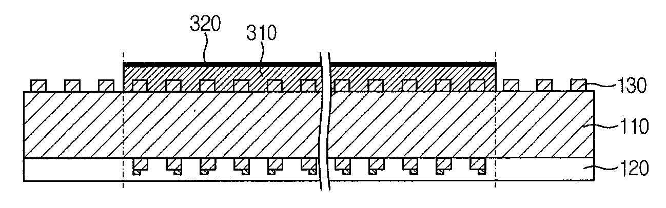
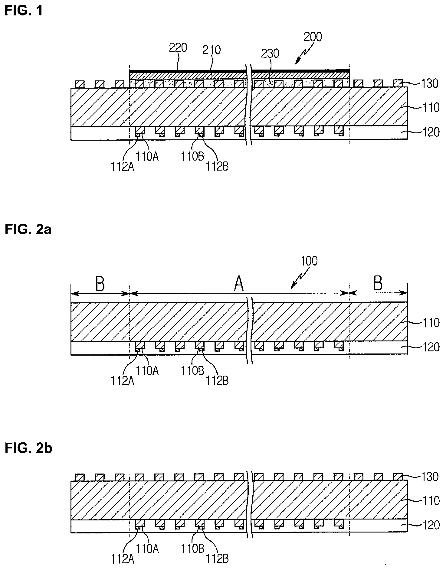
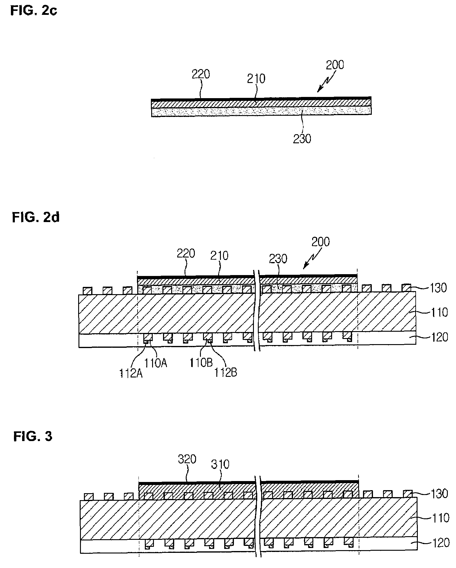
[0022]A plasma display apparatus comprises a plasma display panel, an electromagnetic interference (EMI) shielding layer positioned on the plasma display panel, and a filter positioned on the EMI shielding layer, the filter including an adhesive layer positioned on the EMI shielding layer and a base film layer positioned on the adhesive layer.

[0023]The EMI shielding layer may include a mesh type or a conductive type.

[0024]The filter may be formed in an area except a ground portion of the EMI shielding layer.

[0025]The adhesive layer may comprise at least one of a near infrared ray blocking material, a neon wavelength blocking material, or a selective light absorbing material.

[0026]The filter may further comprise a non-reflective layer positioned on the base film layer.

[0027]A plasma display apparatus comprise a plasma display panel, an electromagnetic...


PUM


Abstract

A plasma display apparatus and a method of manufacturing the same are disclosed. The plasma display apparatus includes a plasma display panel, an electromagnetic interference (EMI) shielding layer positioned on the plasma display panel, and a filter positioned on the EMI shielding layer. The filter includes an adhesive layer positioned on the EMI shielding layer and a base film layer positioned on the adhesive layer.

Description

[0001]This application claims the benefit of Korean Patent Application No. 10-2006-0023102 filed on Mar. 13, 2006, which is hereby incorporated by reference.BACKGROUND[0002]1. Field[0003]This document relates to a display apparatus, and more particularly, to a plasma display apparatus and a method of manufacturing the same.[0004]2. Description of the Related Art[0005]Out of display apparatuses, a plasma display apparatus comprises a plasma display panel and a driver for driving the plasma display panel.[0006]The plasma display panel has the structure in which barrier ribs formed between a front panel and a rear panel forms unit discharge cell or discharge cells. Each discharge cell is filled with an inert gas containing a main discharge gas such as neon (Ne), helium (He) or a mixture of Ne and He, and a small amount of xenon (Xe).[0007]The plurality of discharge cells form one pixel. For example, a red (R) discharge cell, a green (G) discharge cell, and a blue (B) discharge cell for...

Claims


Application Information

Patent Timeline
Patent Type & Authority Applications(United States)
IPC IPC(8): H01J17/49H01J61/40H01J5/16G09F9/00H01J9/20H01J11/44H04N5/64H05K9/00
CPCH01J9/205H01J11/10H05K9/0096H01J2211/446H01J11/44B62D5/062B60Y2306/09
Inventor CHA, HONGRAE
Owner LG ELECTRONICS INC
Why Eureka
Try Eureka