Eureka AIR delivers breakthrough ideas for toughest innovation challenges, trusted by R&D personnel around the world.

Constant voltage regulator for generating a low voltage output

Inactive Publication Date: 2007-09-13
RICOH ELECTRONIC DEVICES CO LTD
View PDF3 Cites 15 Cited by
  • Summary
  • Abstract
  • Description
  • Claims
  • Application Information

AI Technical Summary

Benefits of technology

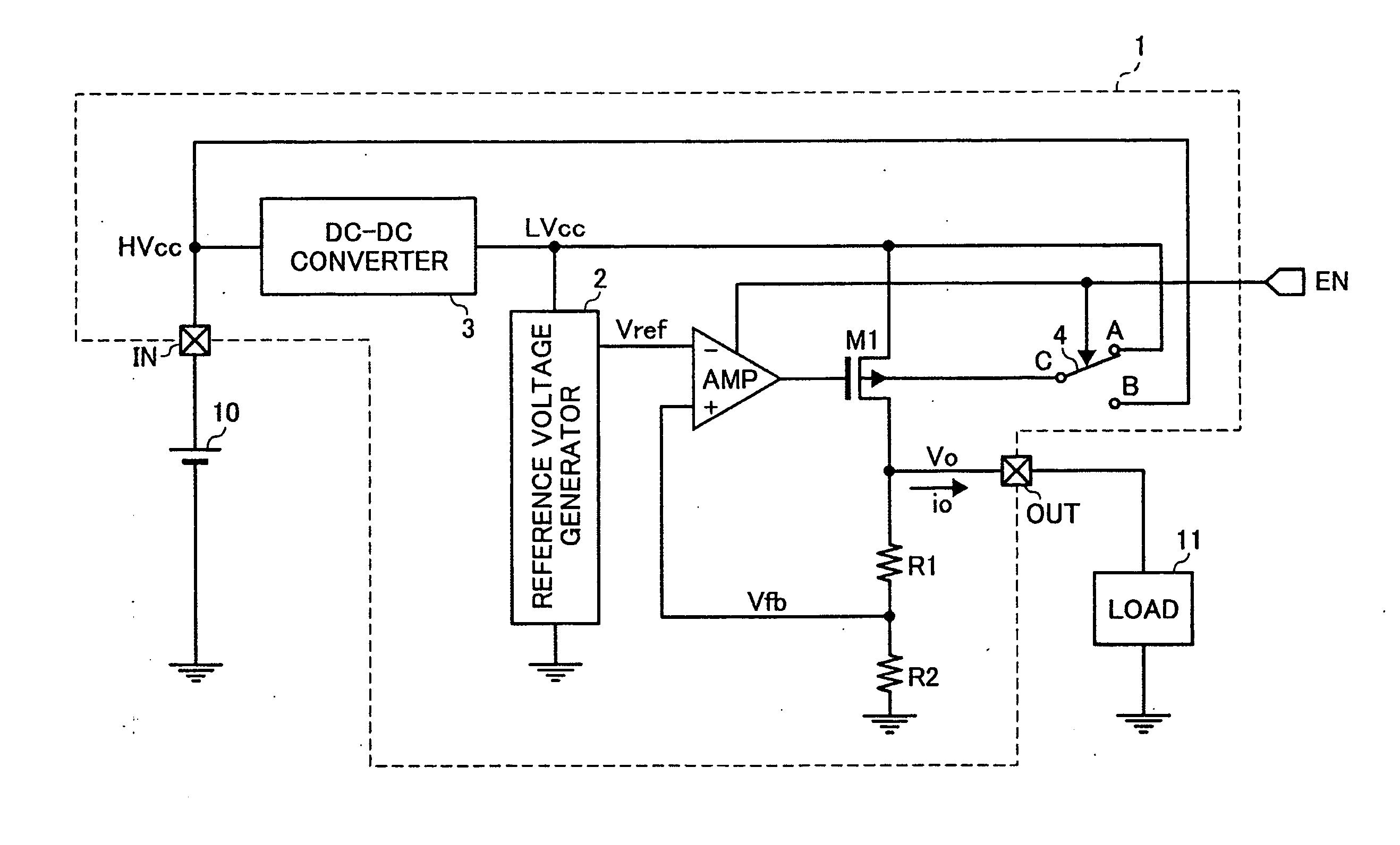
[0027] With the above-described structure, it is possible to apply such a small input-output voltage difference as the output voltage of less than 1.2 volts (or less than 1 volt), for example, and the input voltage of less than 2 volts, for example. Even with such small input-output voltage difference, the constant voltage regulator 1 can prevent an adverse effect of the leak current of the output transistor M1 to the output voltage Vo.
[0034] With the above-described structure, it is possible to apply such a small input-output voltage difference as the output voltage of less than 1.2 volts (or less than 1 volt), for example, and the input voltage of less than 2 volts, for example. Even with such small input-output voltage difference, the constant voltage regulator 1a can prevent an adverse effect of the leak current of the output transistor M1 to the output voltage Vo.

Problems solved by technology

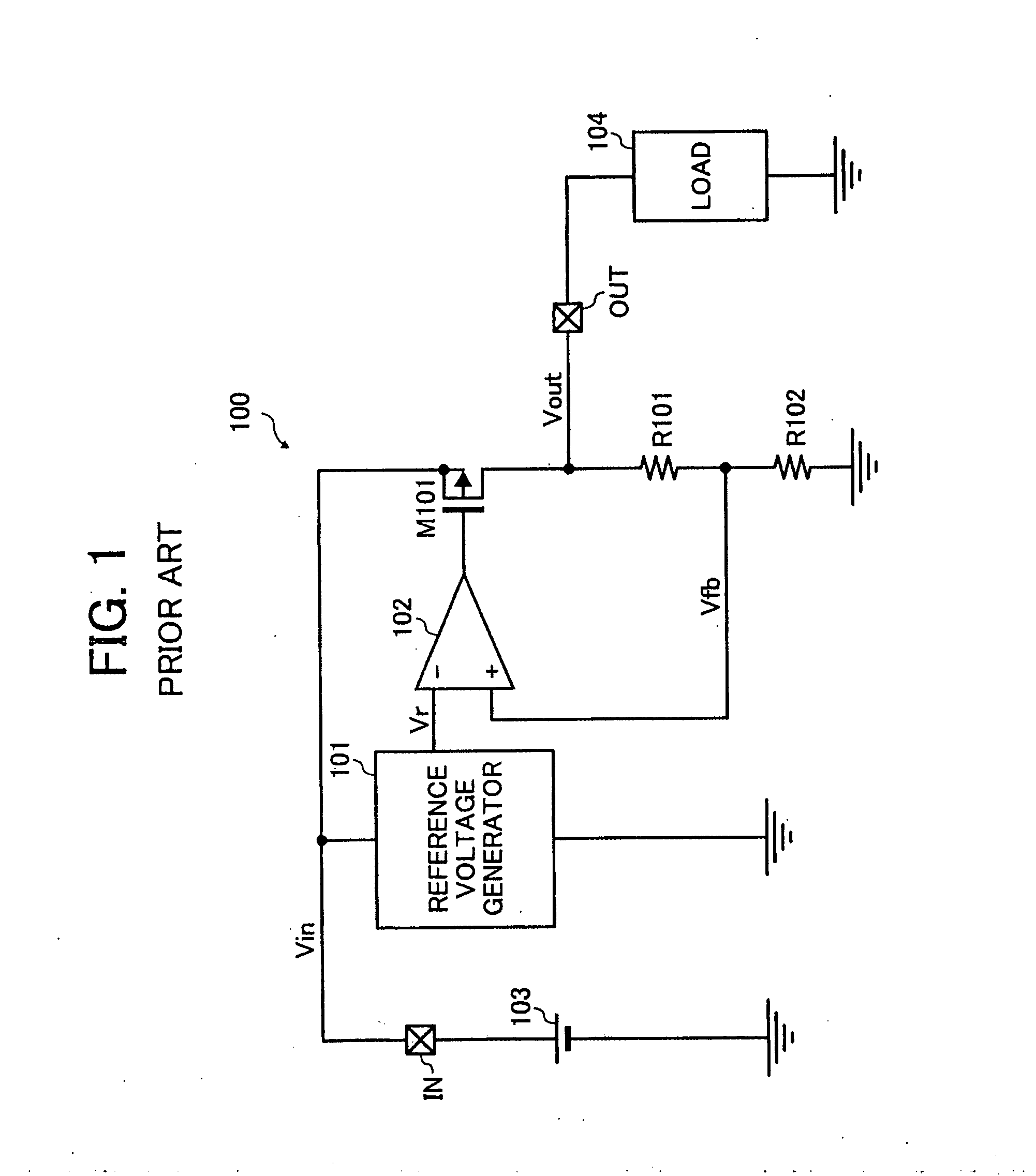
It is generally known that a MOS (metal oxide semiconductor) transistor having a relatively low threshold voltage adversely increases a leak current when turned off.
As a result, the constant voltage regulator 100 cannot be turned off.
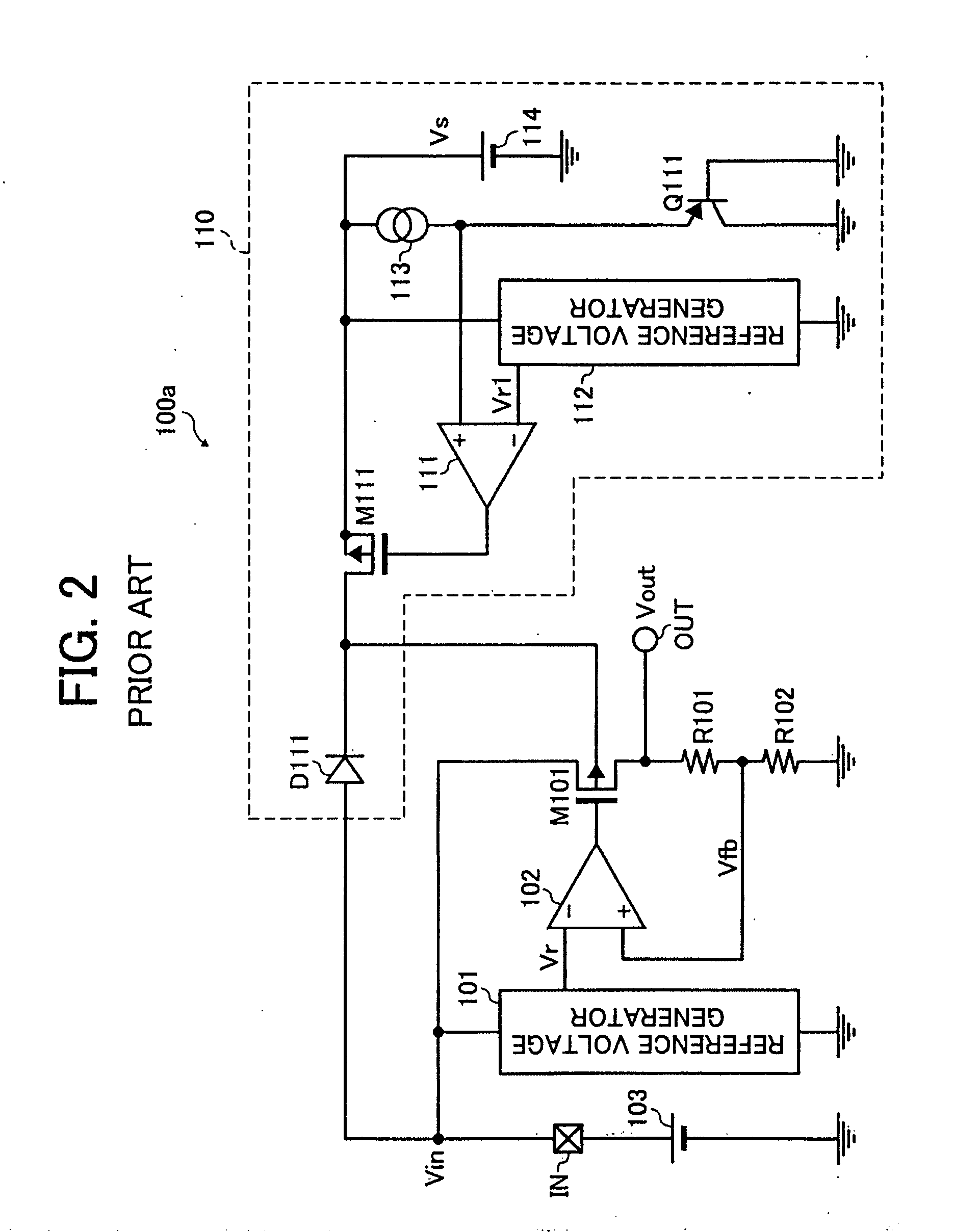
However, the constant voltage regulator 100a produces another problem.
That is, it is a dilemma.

Method used


Image

  • Constant voltage regulator for generating a low voltage output
  • Constant voltage regulator for generating a low voltage output
  • Constant voltage regulator for generating a low voltage output

Examples


Embodiment Construction

[0018] In describing preferred embodiments illustrated in the drawings, specific terminology is employed for the sake of clarity. However, the disclosure of this patent specification is not intended to be limited to the specific terminology so selected and it is to be understood that each specific element includes all technical equivalents that operate in a similar manner. Referring now to the drawings, wherein like reference numerals designate identical or corresponding parts throughout the several views, particularly to FIG. 3, a constant voltage regulator 1 according to an embodiment of the present invention is explained.

[0019] As illustrated in FIG. 3, the constant voltage regulator 1 includes an input terminal IN and an output terminal OUT. The constant voltage regulator 1 is connected to a direct-current power source 10 to receive an input voltage HVcc of the direct power source 10 and is configured to generate an output voltage Vo connected to the input terminal IN and to ou...


PUM


Abstract

Constant voltage regulator includes an output terminal, an output transistor, an output voltage controller, and a switching circuit. The output terminal outputs a first voltage to an external host apparatus. The output transistor outputs a current in accordance with a signal. The output voltage controller amplifies a difference between a reference voltage and a feedback voltage produced in proportion to the first voltage, and outputs the amplified voltage to the control gate of the output transistor. The switching circuit selectively outputs one of a second voltage greater than the first voltage and a third voltage greater than the second voltage to a substrate gate of the output transistor in response to an operation mode switchable between a first mode in which an output current to the external host apparatus is smaller than a predetermined value and a second mode in which the output current is greater than the predetermined value.

Description

BACKGROUND OF THE INVENTION [0001] 1 Field of the Invention [0002] The present invention generally relates to a constant voltage regulator, and more particularly to a constant voltage regulator that generates a relatively low voltage output and is capable of suppressing a leak current from an output transistor. [0003] 2 Discussion of the Related Art [0004] As one example of a background constant voltage regulator, FIG. 1 illustrates a background constant voltage regulator 100 which includes a reference voltage generator 101, an error amplifier 102, an output transistor M101, and resistors Rl and R2. The output transistor M101 includes a PMOS (p-channel metal oxide semiconductor) transistor. The output transistor M101 receives a control signal at its gate terminal so as to convert an input voltage Vin to an output voltage Vout to be supplied to a load 104 (e.g., an external host apparatus) through an output terminal OUT. The resistors Rl and R2 are connected in series between the out...

Claims


Application Information

Patent Timeline
IPC IPC(8): G05F1/00
CPCG05F1/56H02M2001/0045H02M3/156H02M1/0045G05F3/24
Inventor ITOH, KOHZOH
Owner RICOH ELECTRONIC DEVICES CO LTD
Why Eureka
Eureka Blog
Learn More