Intelligent fault detector system and method

a fault detector and intelligent technology, applied in the direction of electrical devices, emergency protective arrangements for limiting excess voltage/current, process and machine control, etc., can solve the problems of prolonging the time when customers are without service, difficult to determine the extent of the problem, and affecting the detection effect of faults, so as to reduce the time to respond and the effect of reducing the response time to the faul

Active Publication Date: 2007-09-13
ACLARA TECH LLC
View PDF31 Cites 61 Cited by
  • Summary
  • Abstract
  • Description
  • Claims
  • Application Information

AI Technical Summary

Benefits of technology

[0007]The invention requires that when a fault is sensed to have occurred, that the amplitude of the fault be measured so a determination can be made as to whether the fault was a medium voltage (MV) fault, or a low voltage (LV) fault. Next, the pattern of the fault signature is examined, together with the change in load, both before and after the fault, so to determine the type of protective device that triggered in reaction to the fault. Based upon the foregoing analysis, and a knowledge of the connectivity (number and location) of electrical meters within the distribution system, a population of meters to be polled is determined. By polling the identified population, a map of the extent of the outage is readily determined, and the time to respond to the fault and restore service is greatly reduced.
[0008]Further embodiments of the invention may not require reliance on the above information, but rather may rely on the knowledge that a fault has occurred, and on which electrical conductors within the distribution system. In this embodiment, even though there may be a larger population of meters to be polled, fast polling techniques incorporated within the TWACS enable polling of meters in blocs of 256, for example, and this allows the polling to be done relatively quickly so that response time to the fault is still greatly reduced.

Problems solved by technology

A drawback with the current protocol for detecting the outages is that the polling needs to be done continuously; or, the polling needs to be triggered in response to an event (outage) so that the scope of the event can be determined, and subsequently the extent of restoration of the power distribution disrupted by the event.
However, determining when to poll in response to a new outage is often problematical.
If polling is done too soon, the extent of the problem may not be readily determined.
Too late, and response to the problem may be delayed, prolonging the time when customers are without service.

Method used


Image

  • Intelligent fault detector system and method
  • Intelligent fault detector system and method
  • Intelligent fault detector system and method

Examples


Embodiment Construction

[0019]The following detailed description illustrates the invention by way of example and not by way of limitation. This description will clearly enable one skilled in the art to make and use the invention, and describes several embodiments, adaptations, variations, alternatives and uses of the invention, including what I presently believe is the best mode of carrying out the invention. As various changes could be made in the above constructions without departing from the scope of the invention, it is intended that all matter contained in the above description or shown in the accompanying drawings shall be interpreted as illustrative and not in a limiting sense.

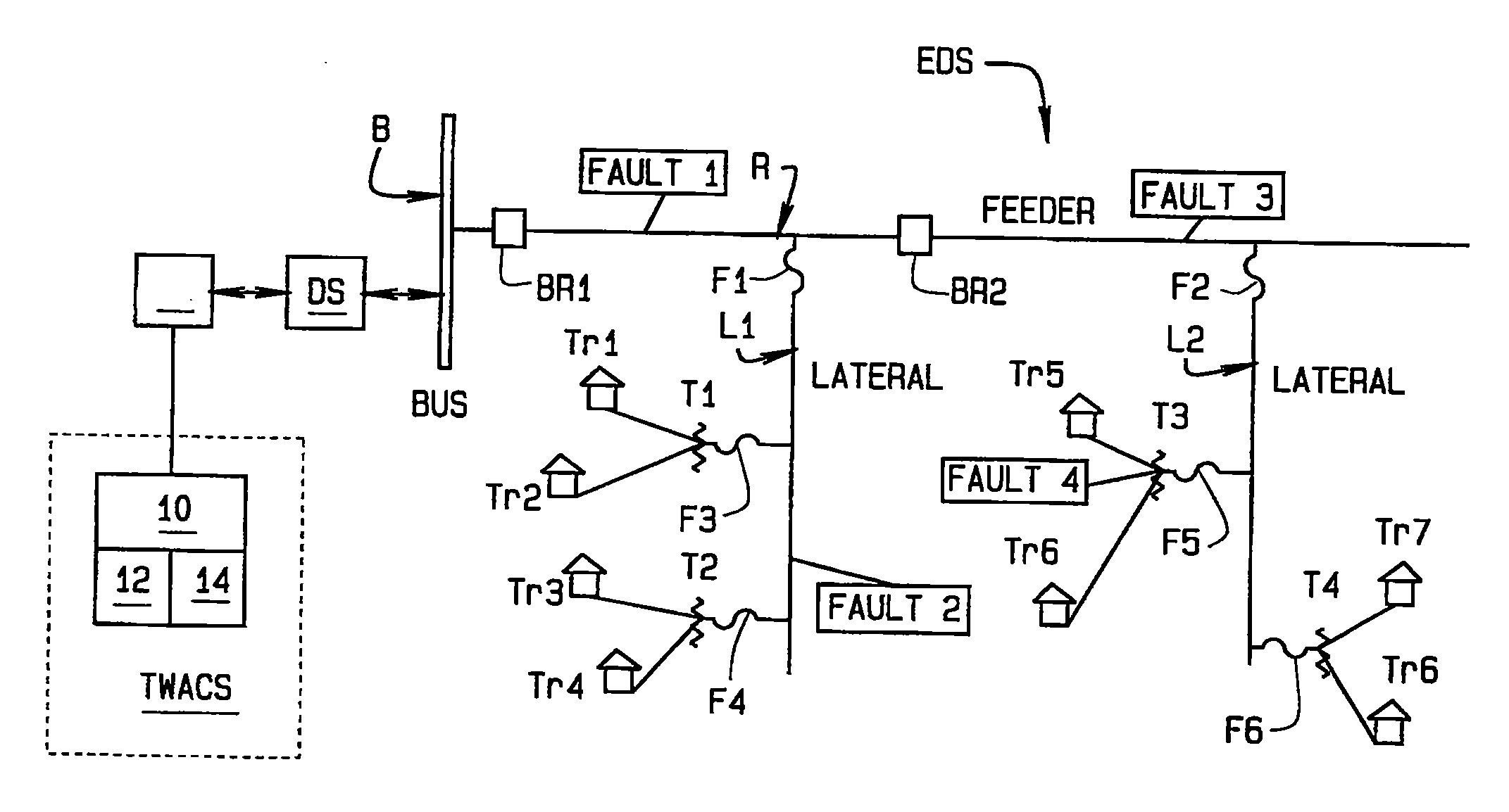
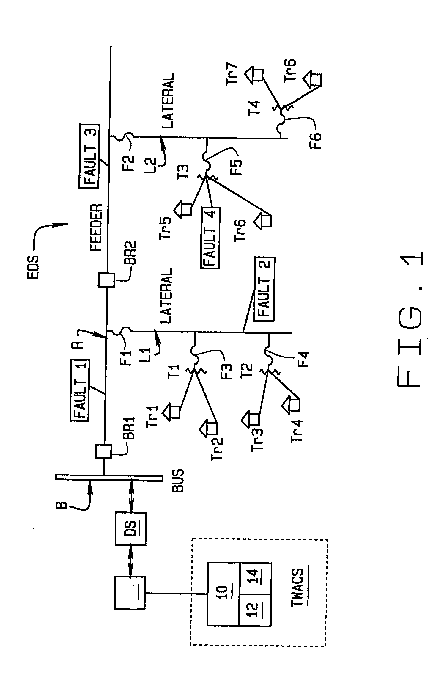
[0020]Referring to FIG. 1, a portion of an electrical distribution system or power distribution network EDS is illustrated. As shown in the Fig., electrical current flows through a bus B to a feeder R, and through the feeder to laterals L1, L2. A circuit breaker BR1, BR2, etc., is interposed in the feeder between the juncture ...


PUM


Abstract

A quick response system incorporated in a TWACS for mapping an outage in an electrical distribution system without having to continuously poll the electrical meters connected to the system. In a primary embodiment of the invention when a fault is sensed to have occurred, the amplitude of the fault is measured to determine if the fault is a medium voltage fault, or a low voltage fault. The pattern of the fault signature and change in load, both before and after the fault, are examined to determine what protective device was triggered by the fault. Using this information, and knowledge of the number and location of electrical meters connected in the distribution system, a population of meters to be polled is determined. By polling the identified population, a map of the extent of the outage is readily determined, and the time to respond to the fault and restore service is reduced.

Description

CROSS-REFERENCE TO RELATED APPLICATIONS[0001]This application claims priority to U.S. Patent Application No. 60 / 780,152 filed Mar. 8, 2006 and is incorporated hereby by reference.STATEMENT REGARDING FEDERALLY SPONSORED RESEARCH[0002]Not Applicable.BACKGROUND OF THE INVENTION[0003]This invention relates to the detection and characterization of a fault occurring in an electrical or power distribution system; and, more particularly, to a system and method incorporated in a two-way automated communications system or TWACS® to identify affected power lines including a particular bus, feeder, phase, etc., to selectively poll transponders installed with electrical meters at facilities to which the power is supplied to quickly identify and map the extent of an outage occurring anywhere within the system.[0004]TWACS technology, various aspects of which are described, for example, in U.S. Pat. Nos. 6,940,396, 5,933,072, 5,486,805, 5,262,755, 4,963,853, 4,918,422, and 4,914,418, has been found...

Claims


Application Information

Patent Timeline
Patent Type & Authority Applications(United States)
IPC IPC(8): H02H9/06
CPCH02H7/261H04B2203/5433H04B3/542
Inventor MAK, SIOE T.
Owner ACLARA TECH LLC
Why Eureka
Try Eureka