Multi-Speed Sprocket Assembly

a multi-speed, sprocket technology, applied in the direction of hoisting equipment, belt/chain/gearing, portability lifting, etc., can solve the problems of extension of the crossing chain section, chain slides off the ramp and is displaced, and the solution is sensitive to dirt, so as to achieve the effect of not being sensitive to dir

Inactive Publication Date: 2007-09-13
SRAM
View PDF13 Cites 9 Cited by
  • Summary
  • Abstract
  • Description
  • Claims
  • Application Information

AI Technical Summary

Benefits of technology

[0009]The object of the invention is to provide a multi-speed sprocket assembly that ensures reliable shifting even in the case of small gradations between gear steps, is also suitable for shifting chains with different structures, and, moreover, is not sensitive to dirt.
[0010]The radial guide, which is important for proper shifting, is attained by adapting the one crossing chain joint between the rear tooth flank of the trailing tooth of the smaller sprocket and the front tooth flank of the leading tooth of the larger sprocket. The axial guide results from the engagement of the trailing tooth between the link plates of the trailing chain link preceding the crossing chain link in the travel direction of the chain. Here, an allowance is made based on the shifting configuration with the leading tooth on the interior of an outer link plate of the first link connection (referred to in the following as an “outer link plate configuration”), the crossing chain must be displaced to the smaller sprocket by the thickness of the leading tooth in order to arrive in the alternate configuration (referred to in the following as an “inner link plate configuration”) with the leading tooth to be adjacent to the exterior of an inner link plate of the leading chain link. Because according to the invention only one chain link is provided between the leading tooth of the larger sprocket and the trailing tooth of the smaller sprocket, the trailing tooth in the outer link plate configuration is also located between two outer link plates of the trailing chain link such that, here, the chain may be displaced relatively far in the axial direction toward the large sprocket (maximally up to the stop on the inner side of the corresponding outer link plate). In the inner link plate configuration, on the other hand, the trailing tooth is located between two inner link plates with the axial play of the chain on the trailing tooth having been reduced by the thickness of one inner link plate. During the shifting process in the outer link plate configuration, the shifting chain, with engagement only on the trailing tooth, is therefore able to be displaced by the derailleur further toward the larger sprocket than in the inner link plate configuration such that, as the sprockets continue to rotate, the leading chain link arrives on the appropriate side of the leading tooth. This results in a guidance of the chain, and therefore a proper shifting operation, for both configurations.
[0012]It is preferable to provide for the larger sprocket to have a region that has been removed to form the double spacewidth with such a shape that the larger sprocket, viewed in the axial direction, does not overlap at all with the crossing chain link. For one, this results in a very cost-effective production because cutting out or stamping out is more cost-effective than, for example, punching processes. An advantageously low weight results as well.
[0014]In further embodiments of the invention, the larger sprocket has a recess, preferably a stamped recess, in an overlap region with the link plates of the trailing link plate pair to provide a clearance between the recess and the trailing link plate pair. In particular in the case of small sprockets, there may be space problems for the link plates of the trailing chain link that were cleared by the recess. Here as well, a clearance is provided between the recess and the trailing link plate pair in order to attain the advantages of the invention, namely compatibility with various models of shifting chains and insensitivity to dirt. According to the invention, an axial guide through the base of the recess is not necessary, because the axial guidance is ensured by the trailing tooth of the smaller sprocket engaging in the trailing plate pair.

Problems solved by technology

However, it has been shown that, under certain conditions, the chain slides off of the ramp and is displaced in the direction of the small pinion.
This leads to an extension of the crossing chain section, which is comprised of two chain links, with the result of faulty shifting function.
The above solutions are sensitive to dirt because dirt between the radial or lateral guide surface and the link plate may lead to a malfunction.

Method used


Image

  • Multi-Speed Sprocket Assembly
  • Multi-Speed Sprocket Assembly
  • Multi-Speed Sprocket Assembly

Examples


Embodiment Construction

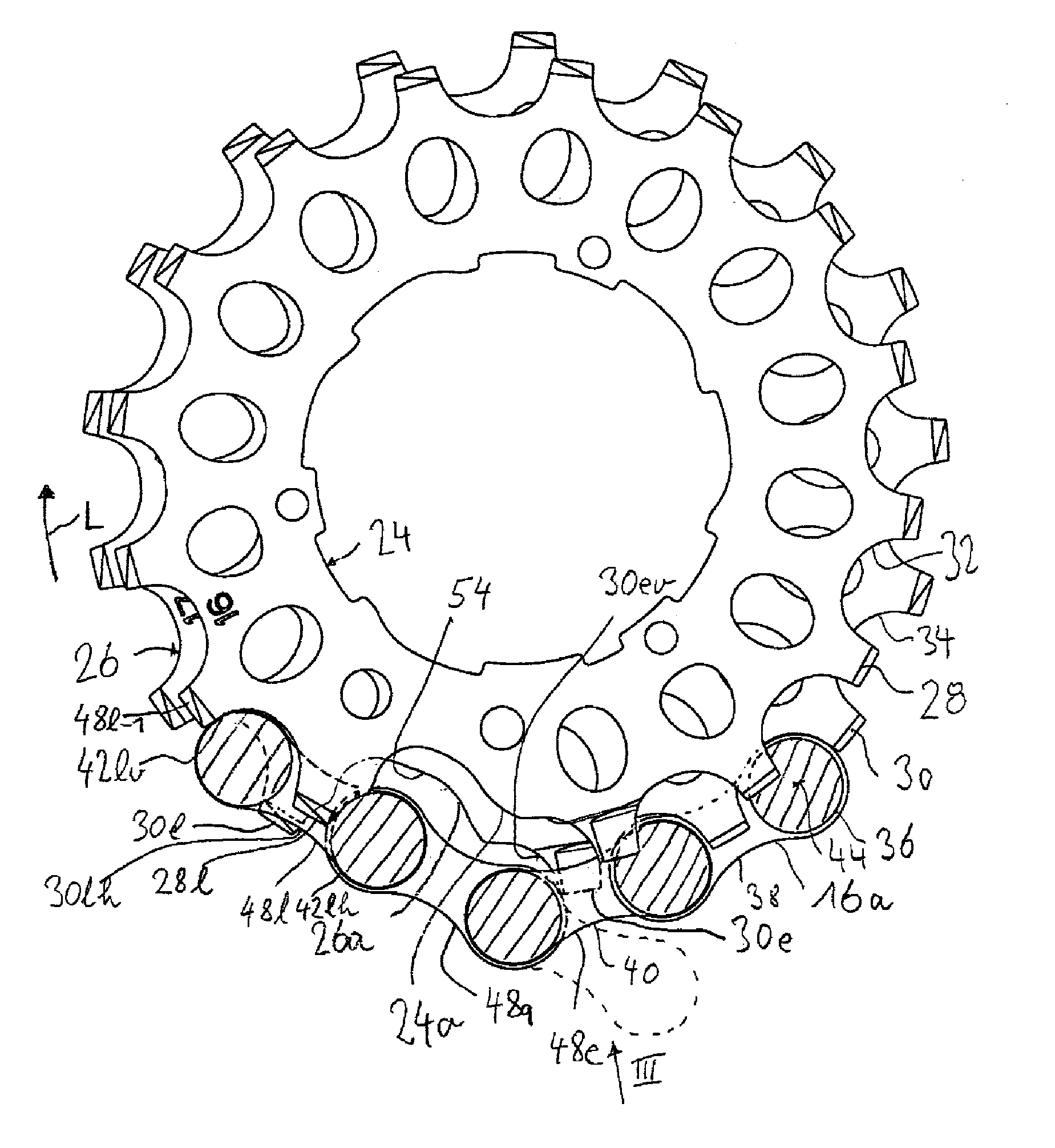
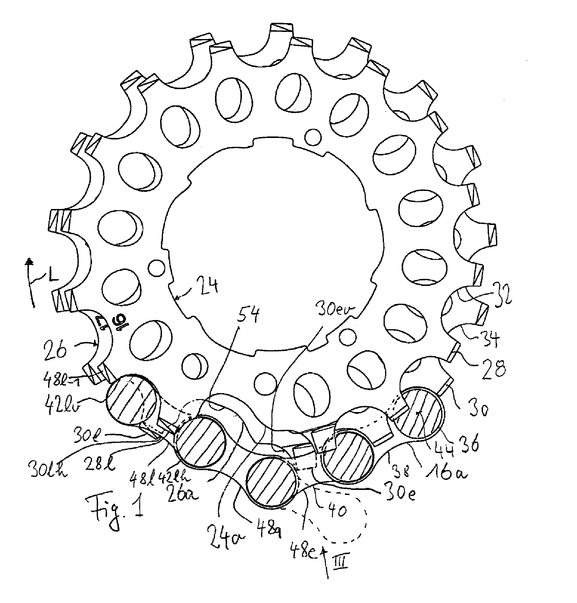
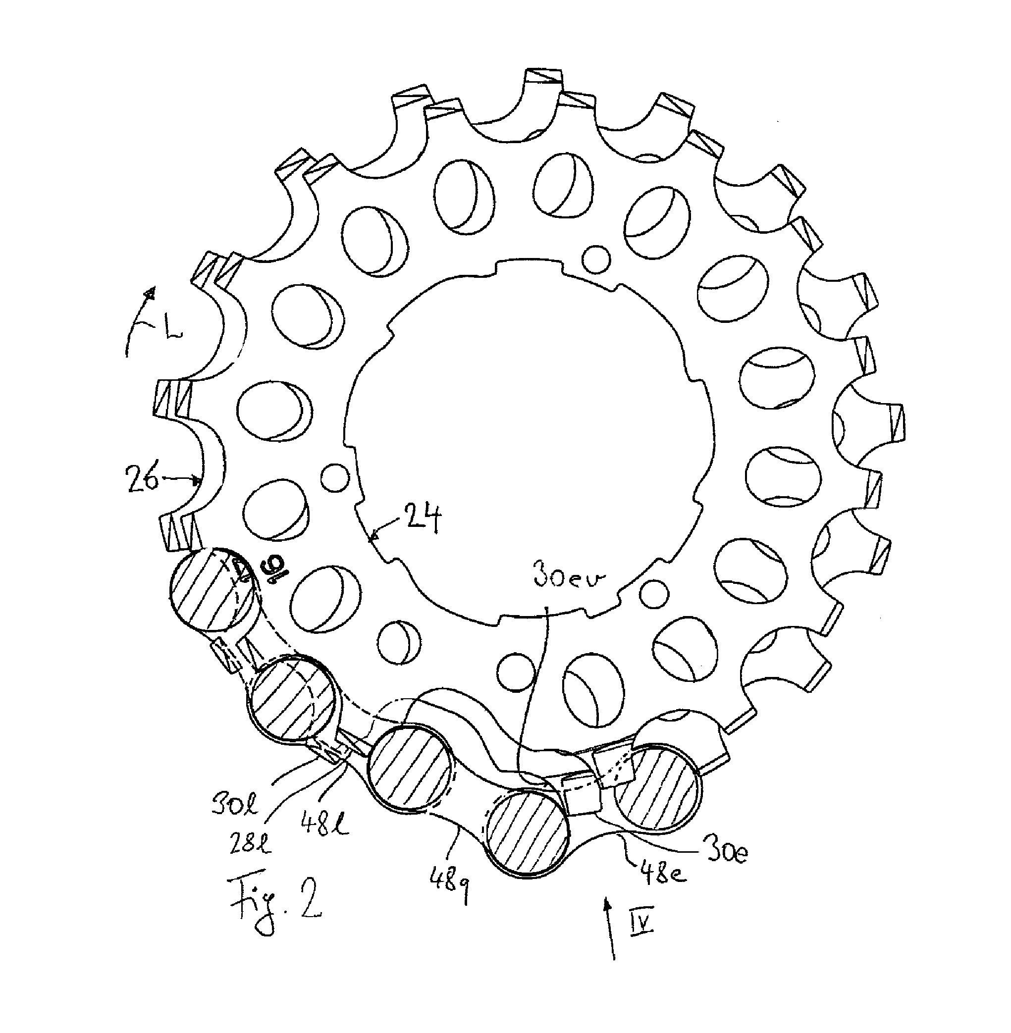
[0032]FIGS. 1-4 illustrate a multi-speed sprocket assembly 18 for a bicycle shifting system according to one embodiment of the present invention. Looking to FIG. 10, the bicycle shifting system 10 generally include a front sprocket assembly 12 driven by pedals 14, a rear sprocket assembly 18 connected to a wheel hub (not shown) and a bicycle chain 16 connecting the front and rear sprocket assemblies 12, 18.

[0033]In the example shown, the front sprocket assembly 12 includes two sprockets; it is also generally possible to provide three sprockets. A front derailleur 20 is used to displace the chain from one sprocket to the other. Correspondingly, a rear derailleur 22 is also arranged behind the rear sprocket assembly 18. Each of the two derailleurs 20 and 22 is provided in the intake area of the chain 16 such that it is possible to shift the chain between the sprockets in the desired manner.

[0034]As described below with reference to FIGS. 1 to 9, the invention has to do with an improve...


PUM


Abstract

A multi-speed sprocket assembly is suggested, including at least two sprockets, with both sprockets having at least one common upshift transitional region in which, when the chain is displaced from the smaller sprocket to the larger sprocket for the purpose of shifting gears, the chain leaves the smaller sprocket, with a trailing tooth of the smaller sprocket being the last to engage between a trailing link plate pair of the chain, and moves onto the larger sprocket, with a leading tooth of the larger sprocket either being the first to engage between a first outer link plate pair or being located adjacent to a first inner link plate pair, and with at least the larger sprocket having in its upshift transitional region a double spacewidth created by omitting a tooth, which is immediately followed by the leading tooth. Only one chain link crossing from the smaller sprocket to the larger sprocket is located between the trailing chain link and the leading chain link. The chain roller of the link connection between the crossing chain link and the trailing chain link is located directly across from a rear tooth flank of the trailing tooth of the smaller sprocket. The leading tooth cooperates with a circumferential surface of a link plate of the crossing chain link using its front tooth flank, with the leading tooth being in contact with either the inner surface of an outer link plate or with the outer surface of an inner link plate of the leading chain link. In the region of the double spacewidth, the larger sprocket is embodied in such a way that the crossing chain link comes into contact with the larger sprocket only in the region of the leading tooth.

Description

BACKGROUND OF THE INVENTION[0001]The invention relates to bicycle shifting systems, and more particularly, to a multi-speed sprocket assembly for a bicycle shifting system that ensures proper shifting from a smaller sprocket to a larger sprocket.[0002]Derailleurs, in particular for bicycles, have existed for a long time. In spite of their open and therefore unprotected construction as compared, for example, to hub shifters, derailleurs are very popular due to their high level of efficiency, light weight, and cost-effective structure. In recent times, attempts have been made to improve shifting function, in particular for shifting under load as well as to reduce the gear step by correspondingly increasing the number of sprockets. For example, a ten-gear shifting system has been attempted with ten respective sprockets, with consecutive sprockets differing from one another by only one tooth.[0003]In derailleurs, the most critical issue is shifting up from a smaller sprocket to a larger...

Claims


Application Information

Patent Timeline
Patent Type & Authority Applications(United States)
IPC IPC(8): F16H55/30F16H55/12
CPCB62M9/10
Inventor REITER, MARKUSSCHMIDT, FRANK
Owner SRAM
Why Eureka
Try Eureka