Continuously variable transmission device

a transmission device and variable technology, applied in the direction of friction gearings, gearing elements, friction gearings, etc., can solve the problems of inability to perform stable traction transmission, difficult to set an appropriate traction coefficient, excessive force on the planetary roller, etc., to prevent wear and the like prevent the effect of biting at the screwing area and smooth driving

Active Publication Date: 2016-05-31
MIKUNI CORP
View PDF11 Cites 2 Cited by
  • Summary
  • Abstract
  • Description
  • Claims
  • Application Information

AI Technical Summary

Benefits of technology

[0014]To address the above issues, an object of the present invention is to provide a continuously variable transmission device with which a stable normal force can be obtained at the traction transmission portion in accordance with an output load by automatically balancing the planetary rollers at appropriate positions, the traction transmission portion can be prevented from being locked during deceleration or the like, smooth operation of functional components can be obtained by ensuring an internal lubrication action, a sufficient traction force or a sufficient transmission torque can be ensured, and speed changing can be reliably controlled to a desired transmission ratio, while achieving structural simplification, miniaturization, functional reliability improvement, and the like.

Problems solved by technology

Accordingly, when a contact point of the transmission ring with the planetary roller is varied in position with movement of the transmission ring, balances of normal forces respectively between the input roller and the planetary roller, between the output ring and the planetary roller, and between the transmission ring and the planetary roller are to be lost and an excessive force is exerted on the planetary roller.
Consequently, it is difficult to set an appropriate traction coefficient.
Further, there is a fear that stable traction transmission cannot be performed owing to that variation occurs in the contacting state at the traction transmission region caused by variation of assembling the plurality of planetary rollers and the like.
Further, when once torque transmission is interrupted, there is a fear that a drive torque input from the input shaft is not transmitted to the output shaft and torque transmission cannot be performed as a result.
That is, it is not possible to provide an automatic shift-down function.
Further, in a case that a reverse torque (load torque) such as engine braking is exerted to the output shaft, an excessive thrust load is exerted to the output ring to cause a fear that the traction transmission portion is locked.
Further, in the conventional continuously variable transmission device, no regard is given to circulation of lubricant oil during operation of the traction transmission.
Therefore, there is a fear to cause seizing at bearings and the like.
Further, there is a fear that smooth motion for moving the transmission ring cannot be obtained owing to occurrence of biting, wearing, and the like at a drive force transmission region when the transmission ring is moved.
Furthermore, any measures are not provided for interference between the transmission ring and the movable holder which holds the planetary rollers, and the like.

Method used


Image

  • Continuously variable transmission device
  • Continuously variable transmission device
  • Continuously variable transmission device

Examples


Embodiment Construction

[0053]In the following, embodiments of the present invention will be described with reference to the attached drawings.

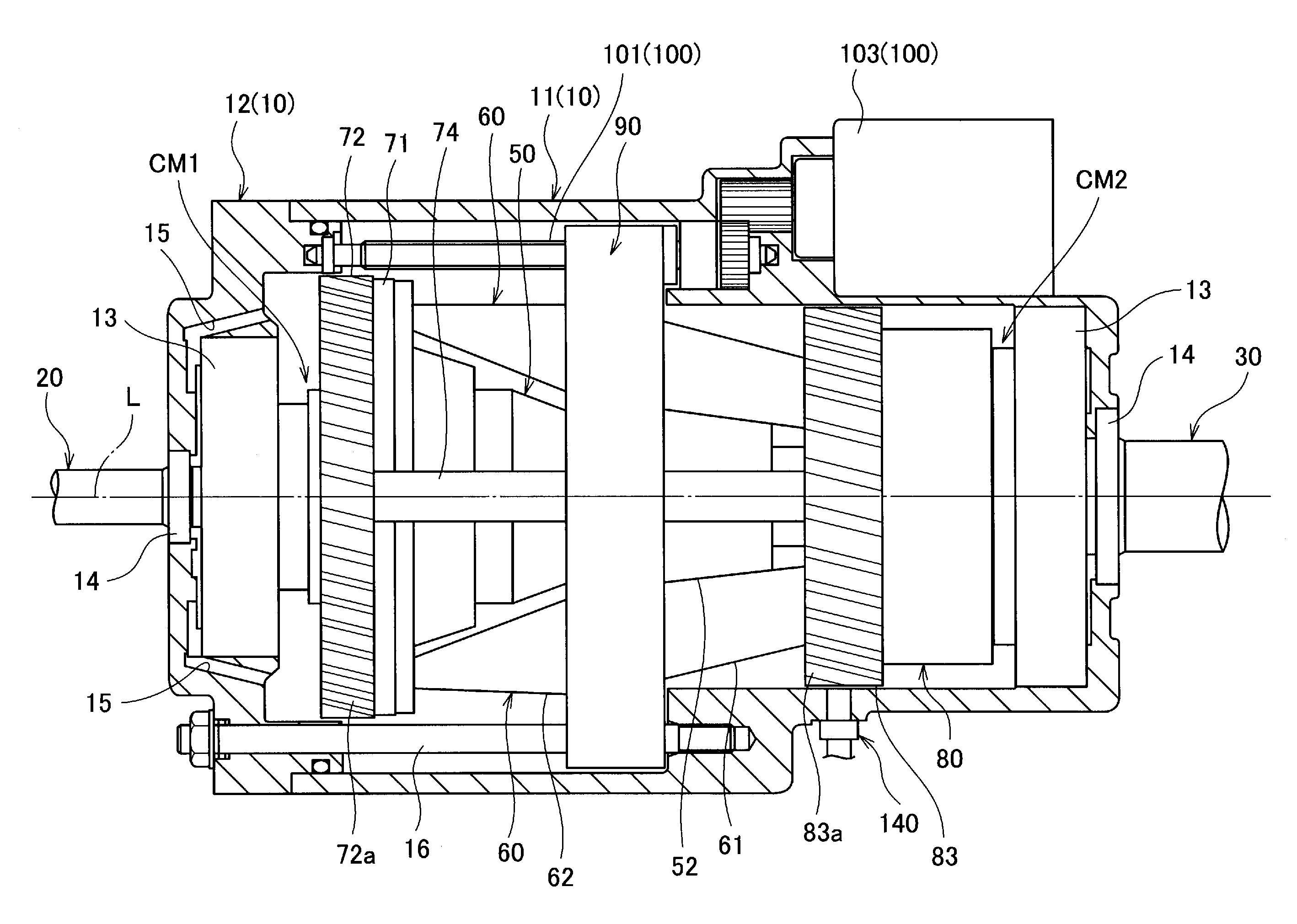
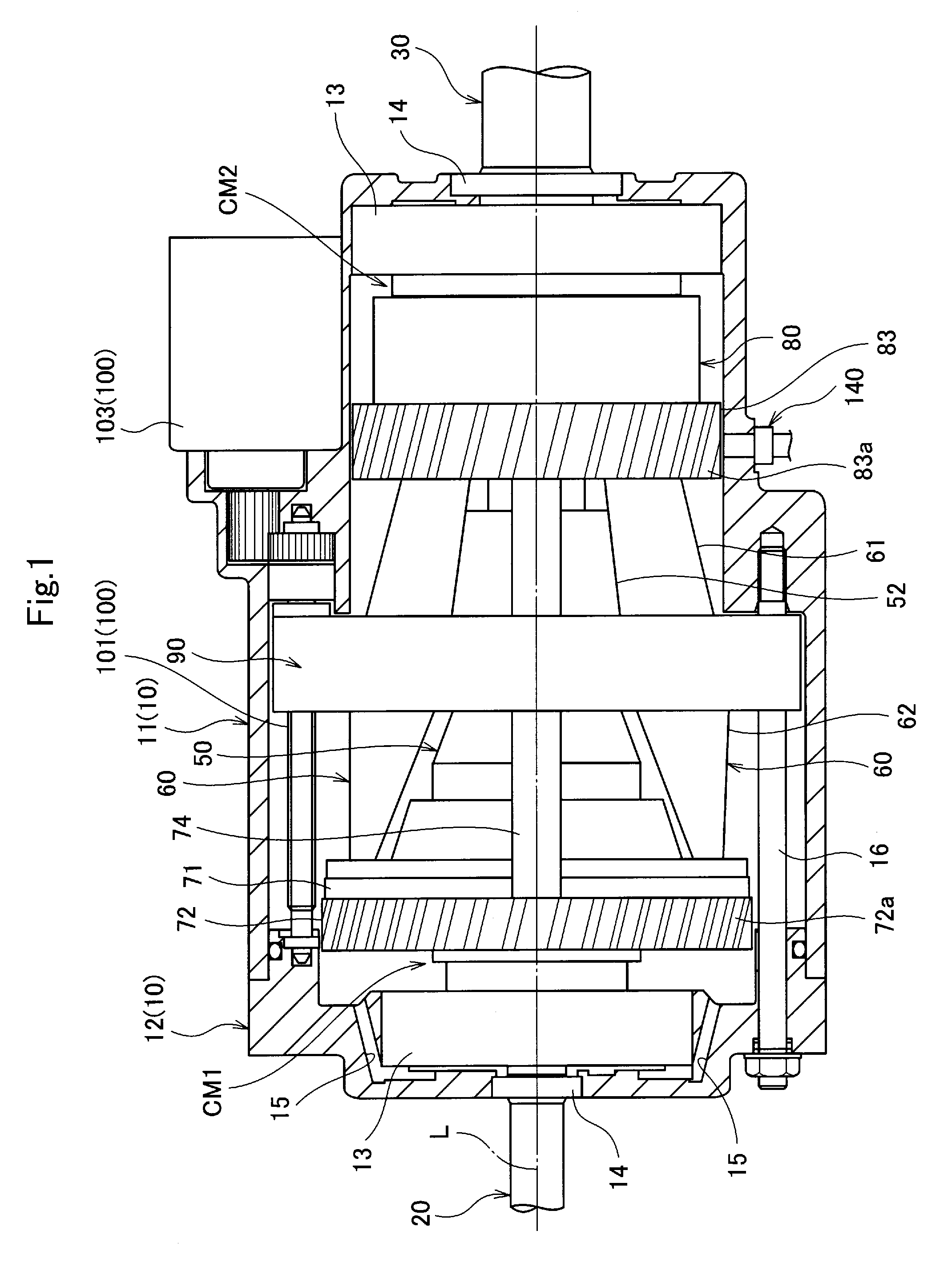
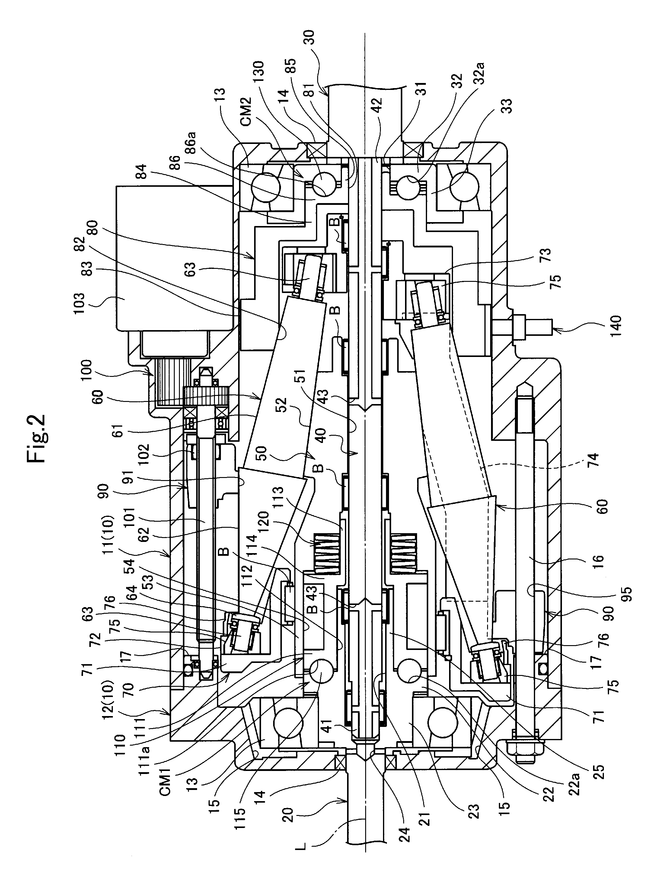
[0054]As illustrated in FIGS. 1 to 3, a continuously variable transmission device includes a housing 10, an input shaft 20 which is rotatably supported by the housing 10 as having a center axial line L, an output shaft 30 which is rotatably supported by the housing 10 coaxially with the input shaft 20 as having the center axis line L, a center shaft 40 which is arranged between the input shaft 20 and the output shaft 30 coaxially therewith (as having the center axis line L), an input roller 50 which is rotatable integrally with the input shaft 20 (as being interlocked therewith), a plurality (in this example, six) of planetary rollers 60 which are rotated as being externally contacted to the input roller 50, a movable holder 70 which holds the plurality of planetary rollers 60 to be capable of rotating about each rotation axis line S and revolving about the center a...


PUM


Abstract

A continuously variable transmission device includes an input shaft, an output shaft, an input roller, an output ring, a transmission ring, a plurality of planetary rollers including a first conical portion externally contacted to the input roller and internally contacted to the output ring and a second conical portion internally contacted to the transmission ring, a movable holder which holds the plurality of planetary rollers to be capable of rotating about each rotating axis line and revolving about the center axis line, and a loading cam mechanism (CM1, CM2) which generates a thrust load. The input roller, the output ring, and the transmission ring are formed so that each face being contacted to the planetary roller is formed to have a convex curved face. The planetary rollers are supported by the movable holder so that an inclination angle of a rotation axis line against the center axis line is variable.

Description

TECHNICAL FIELD[0001]The present invention relates to a continuously variable transmission device which performs transmission to an output shaft with traction drive using a traction force as continuously varying rotation speed of an input shaft, and more particularly, relates to a continuously variable transmission device which continuously performs continuous speed changing using conical planetary rollers.BACKGROUND ART[0002]There has been conventionally known a continuously variable transmission device including an input shaft, an input roller (an inner ring, a drive face, or the like) which is rotated integrally with the input shaft, an output shaft which is arranged coaxially with the input shaft, an output ring (an outer ring, a driven face, or the like) which is rotated as being interlocked with the output shaft, a plurality of cone-shaped planetary rollers (taper rollers, double cones, or the like) which are arranged around a center axis line of the input shaft and the output...

Claims


Application Information

Patent Timeline
Patent Type & Authority Patents(United States)
IPC IPC(8): F16H15/48F16H61/664F16H13/08F16H63/06F16H57/04
CPCF16H13/08F16H57/0434F16H57/0487F16H61/6649F16H63/067F16H15/52F16H57/0428F16H15/54
Inventor SEKIYA, MITSURU
Owner MIKUNI CORP
Why Eureka
Try Eureka