Amplifier composite triple beat (CTB) reduction by phase filtering

a phase filtering and composite filter technology, applied in the field of cable television systems, can solve the problems of reducing the range of cable broadcasting, limiting the length of signal transmission, increasing noise in both forward and back directions, etc., and achieve the effect of reducing the accumulated amplitude of the different ctb distortions

Inactive Publication Date: 2009-01-06
ARRIS ENTERPRISES LLC
View PDF34 Cites 2 Cited by
  • Summary
  • Abstract
  • Description
  • Claims
  • Application Information

AI Technical Summary

Benefits of technology

[0019]The invention reduces the accumulated amplitude of the different CTB distortions produced by power amplifiers in several different types of equipment in the communications link of a cable television system. Both, the CTB distortions in the forward signal between the head-end and the CIUs are reduced and the CTB distortions in the return signals from the CIUs to the head-end are reduced.

Problems solved by technology

The line amplifiers in the coaxial cable network produce distortions that result in additional noise that further limits the length of signal transmission.
In bi-directional transmission, the introduction of return light beams in the optical fiber network results in crosstalk as additional noise that further reduces the range of cable broadcasting.
The line amplifiers must be bi-directional and both the forward and return amplifiers produce distortions that result in increased noise in both the forward and return directions which further limits transmission distance.
The distortions are cumulative as the signal passes through a multitude of power amplifiers from the source of the signal to the CIUs, and the distortions from return signal amplification in the line amplifiers also adds to the distortion of the forward signals.
The result is that signal transmission in bi-directional systems is even more limited by noise than in previous one-directional systems.

Method used


Image

  • Amplifier composite triple beat (CTB) reduction by phase filtering
  • Amplifier composite triple beat (CTB) reduction by phase filtering
  • Amplifier composite triple beat (CTB) reduction by phase filtering

Examples


Embodiment Construction

[0035]In the following description the same labels in different figures indicate similar elements, but similar elements may be identified by different labels for convenience of description.

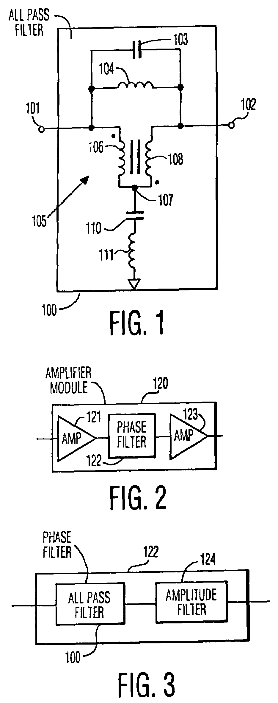
[0036]FIG. 1 illustrates an all pass filter 100 of the invention. The all pass filter includes: an input terminal 101 and an output terminal 102; a capacitor 103 connected between the input and output terminals; an inductor 104 connected between the input and output terminals; a transformer 105 with first windings 106 connected in a direction between the first terminal and a third terminal 107 and the second windings 108 connected in the same direction between the third terminal and the output terminal, the first windings 106 and the second windings 108 being connected in series; and a capacitor 110 and an inductor 111 connected in series between the third terminal and ground. The order of the connection of capacitor 110 and inductor 111 is arbitrary. The location of the dots on transformer 105 in...


PUM


Abstract

In a broadband communication system there are multi-stage power amplifier systems for amplifying the power of radio-frequency (RF) communication signals. Each stage of the amplifier system results in composite triple beat (CTB) distortion, and if the phase of the CTB distortions are approximately the same (i.e. are in-phase), then the amplitudes of the distortions are added (i.e. “20 dB” rule). The amplifier system of the invention includes one or more phase filters positioned in series between the power amplifier stages. The phase filters are adapted to shift the phase of the communication signals, so that the phase of CTB distortions, resulting from the amplification of the communication signals in the amplifier stages between the phase filters, are substantially different (i.e. are out-of-phase). Thus, only the power of the CTB distortions are added (i.e. “10 dB” rule).

Description

CROSS REFERENCE TO RELATED APPLICATION[0001]The present application claims the benefit under 35 USC 120 as a divisional application of utility application Ser. No. 09 / 474,295, filed Dec. 29, 1999, and now granted as U.S. Pat. No. 6,788,169 B1. the disclosure of which is herein incorporated by reference.FIELD OF THE INVENTION[0002]The invention is related to the field of cable television systems and more specifically with amplification of multi-carrier video signals in cable television systems.BACKGROUND OF THE INVENTION[0003]In a cable television system (CATV), television programs are provided at a central head-end. The programs are distributed from the head-end through branching tree-like networks of optical fibers to a multitude of hybrid fiber cable nodes (HFCNs) in respective local communities. Then further distributed from the HFCNs through branching tree-like networks of coaxial cables to customer interface units (CIUs), also called cable terminations.[0004]Currently, many of ...

Claims


Application Information

Patent Timeline
Patent Type & Authority Patents(United States)
IPC IPC(8): H03F1/26H03F1/32H03F3/60H03F3/68H03H7/09H03H7/19H04B3/14H04H20/78H04N7/10H04N7/173H04N7/22
CPCH03F1/32H03F3/602H03H7/19H04B3/146H04N7/102H04N7/17309H03F2200/168H04H20/78
Inventor SCHEMMANN, MARCEL F.MARICEVIC, ZORAN
Owner ARRIS ENTERPRISES LLC
Why Eureka
Try Eureka