
Method for removing bubbles from slurry and device therefor

a technology of removing bubbles and slurry, which is applied in the direction of liquid degasification, separation processes, chemistry apparatus and processes, etc., can solve the problems of difficult to fully remove air bubbles by this method, inefficient removal of slurry from the container, and surface defects, so as to dramatically reduce the time of removing bubbles, the effect of optimizing the removal of bubbles from the slurry and the viscosity of the slurry

Inactive Publication Date: 2007-09-20
NGK INSULATORS LTD
View PDF0 Cites 16 Cited by
  • Summary
  • Abstract
  • Description
  • Claims
  • Application Information

AI Technical Summary

Benefits of technology

[0011]The present invention has been accomplished in view of the problems with the above prior art, and the aims of the present invention is to provide a method for removing bubbles from a slurry and a device therefor capable of efficiently optimizing the removal of bubbles from a slurry and the viscosity of a slurry as well as dramatically reducing the bubble removing time.
[0020]The method for removing bubbles from a slurry and the device therefor according to the present invention can efficiently optimize the removal of bubbles from the slurry and the viscosity of the slurry as well as dramatically reducing the bubble removing time.

Problems solved by technology

However, the method (1) for adding a defoaming agent to a slurry for removing bubbles cannot remove air bubbles in the slurry although it is effective for removal of air bubbles on the surface.
A product prepared using such a slurry causes inner air bubbles to appear in a finish-grinding and polishing processes thus resulting in surface defects.
The method (3) for introducing a slurry into a decompressed container per batch, and after decompression and deaeration, taking the slurry out of the container is extremely inefficient because deaeration takes place per batch and is thus not suited for mass-production.
It is difficult for this method to fully remove air bubbles when the viscosity of the slurry is high.
Moreover, the slurry is exposed to vacuum for a prolonged time, which may substantially change the water amount due to drying.
In addition, the viscosity of a slurry is raised and becomes hard to handle if air bubbles are completely removed.
Thus, air bubbles having such a fine diameter that a problem does not occur when a product is finished are dispersed, ideally, but this goal is hard to attain with the methods (1) to (3).

Method used


Image

  • Method for removing bubbles from slurry and device therefor
  • Method for removing bubbles from slurry and device therefor
  • Method for removing bubbles from slurry and device therefor

Examples


example

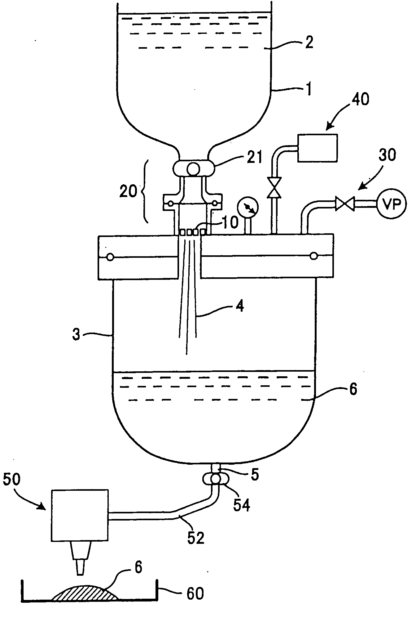
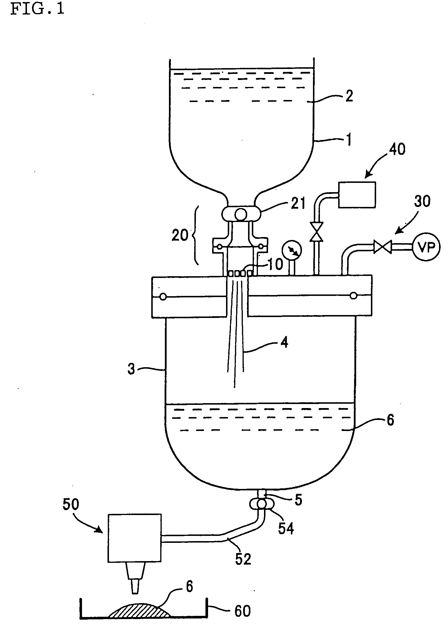
[0047]The slurry from which bubbles were removed was obtained from the above-mentioned slurry containing bubbles to be removed, by using the bubbles removing device shown in FIG. 1. The bubble removing time was 50 L / 5 minutes and the then degree of vacuum of the slurry tank 3 was 6.7 kPa (50 Torr). The bubble diameter distribution with respect to the amount of bubbles in the slurry containing bubbles was measured using a mercury porosimeter. The result is shown in FIG. 6.


PUM

PropertyMeasurementUnit
Pressureaaaaaaaaaa
Pressureaaaaaaaaaa
Diameteraaaaaaaaaa

Abstract

There is disclosed a method for removing bubbles from a slurry and a device therefor capable of efficiently optimizing the removal of bubbles from a slurry and the viscosity of the slurry as well as dramatically reducing the bubble removing time. The device for removing bubbles from a slurry comprises a hopper 1 for charging a predetermined amount of slurry 2 including liquid and a high concentration of solid material agitated and dispersed in the liquid with the slurry containing bubbles to be removed therein; a bubble removing unit 20 disposed downstream of the hopper 1 and having a bubble removing plate 10 disposed downstream of the hopper 1 for discharging the slurry2 containing bubbles to be removed therein in the form of and noncontact filaments or noodles; a slurry tank 3 connected downstream of the bubble removing unit 20; a vacuum unit 30 for evacuating the slurry tank 3 when the bubble removing unit 20 is used; and an air introduction unit 40 for introducing air for pressure-delivering the slurry 6 which is contained in the slurry tank 3 from the bubble removing unit 20 with bubbles removed to the outside.

Description

BACKGROUND OF THE INVENTION[0001]1. Field of the Invention[0002]The present invention relates to a method for removing bubbles from a slurry and a device therefor.[0003]2. Description of the Related Art[0004]When a high concentration of solid material is agitated and dispersed in the liquid, a slurry can be obtained as a fluidized suspension. In particular, a slurry used for a ceramic product or a ceramic repairing material, such as a slurry cast material, a plugging material for a honeycomb structure filter or an outer peripheral coating material for a honeycomb structure, comprises a ceramic slurry which is manufactured from a ceramic powder (solid material) as a starting raw material. The ceramic powder is dispersed in a solvent to prepare a ceramic slurry. Air is included in the processes of mixing, agitation, kneading, dispersion and the like and air bubbles are dispersed and mixed into the slurry.[0005]For example, in case the slurry prepared above is used for a ceramic produc...

Claims


Application Information

Patent Timeline
IPC IPC(8): B01D19/00
CPCB01D19/0036
Inventor MIYASHITA, KOICHIICHIKAWA, YUKIHITO
Owner NGK INSULATORS LTD
Learn More