[0017]It is another object of the invention to provide a fuel injection control apparatus for a multi-cylinder
internal combustion engine mounted in a vehicle which is designed to ensure the stability in running the vehicle at a minimized load on the apparatus.
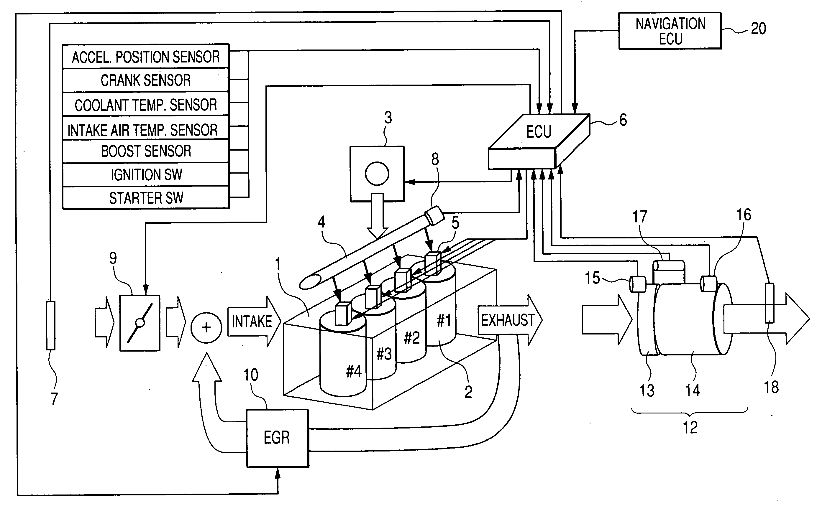
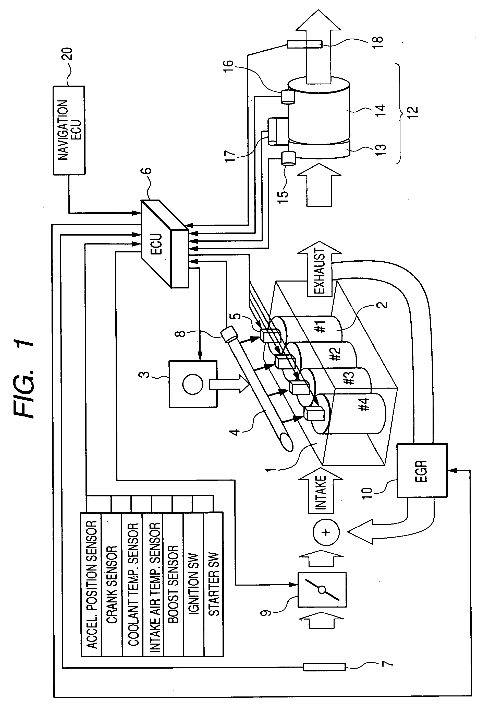
[0018]According to one aspect of the invention, there is provided a fuel injection control apparatus which may be employed in automotive multi-cylinder
diesel engine. The fuel injection control apparatus comprises: (a) injectors each of which, when energized, works to spray fuel into one of cylinders of an engine of a vehicle; (b) an operating condition determining circuit working to determine preselected operating conditions of the engine and the vehicle; and (c) a controller working to schedule execution of a sequence of multiple injections of the fuel into each of the cylinders through control of a corresponding one of the injectors in each
operating cycle of the engine based on the operating conditions, as determined by the operating condition determining circuit. The controller determines whether an overlapping condition where events of any two of the injections scheduled to be executed in any two of the cylinders overlap in time with each other is met or not. When the overlapping condition is determined to be met, the controller determines which of the two of the injections overlapping each other should be rescheduled based on the operating condition of the vehicle, as determined by the operating condition determining circuit, and reschedules execution of one of the two of the injections, as determined to be rescheduled, so as to eliminate overlap with any of the events of the injections. Specifically, when at least one of the scheduled events of the sequence of injections to be executed in any one of the cylinders of the engine is in
coincidence in time with that to be executed in another of the cylinders, the controller reschedules the execution of either of the overlapping events of the injections so as to eliminate the overlap with any of the events of the injections to be executed in the other cylinders without sacrificing running conditions of the vehicle, thereby avoiding the undesirable application of load on the apparatus or the
delay in activating the injectors, as described above.
[0021]The controller works to monitor the operating condition of the vehicle, as determined by the operating condition determining circuit, to determine whether drive torque is required by the vehicle or not. When it is determined that the duration of one of the first sub-injection and the second sub-injection scheduled to be executed in one of the cylinders overlaps that of the main injection scheduled to be executed in another of the cylinders and that the drive torque is determined to be required by the vehicle, the controller reschedules the execution of the one of the first sub-injection and the second sub-injection, as determined as overlapping in the duration thereof with the main injection, so as to eliminate overlap with any of the events of the injections. Specifically, the controller prioritizes the execution of the main injection to ensure the stability in driving the vehicle.
[0022]The controller may monitor the operating condition of the vehicle, as determined by the operating condition determining circuit, to determine whether no drive torque is required by the vehicle or not. When it is determined that the duration of one of the main injection and the first sub-injection scheduled to be executed in one of the cylinders overlaps that of the second sub-injection scheduled to be executed in another of the cylinders and that no drive torque is determined to be required by the vehicle, the controller reschedules the execution of the one of the main injection and the first sub-injection, as determined as overlapping in the duration thereof with the second sub-injection, so as to eliminate overlap with any of the events of the injections.
[0024]The controller may work to monitor the operating condition of the vehicle, as determined by the operating condition determining circuit, to determine whether the vehicle is acceleration or not. When it is determined that the duration of the second sub-injection scheduled to be executed in one of the cylinders overlaps that of the first sub-injection scheduled to be executed in another of the cylinders and that the vehicle is accelerating, the controller reschedules the execution of the second sub-injection, as determined as overlapping in the duration thereof with the first sub-injection, so as to eliminate overlap with any of the events of the injections. Usually, when the vehicle is accelerating, the engine is required to produce the drive torque. Therefore, the controller prioritizes the execution of the first sub-injection to promote the
combustion of the fuel in the engine.
[0025]When it is determined that the second sub-injection, as scheduled to be executed in one of the cylinders, overlaps that of one of the main injection, the first sub-injection, and the second sub-injection, as scheduled to be executed in another of the cylinders, the controller may omit at least a portion of the duration of the second sub-injection, as determined as overlapping that of the one, so as to eliminate overlap with the one, and also determine a duration of the second sub-injection scheduled to be executed subsequently in one of the cylinders so as to compensate for the omitted portion of the duration of the second sub-injection. Specifically, the controller compensates for a lack of the fuel arising from the omission of the duration of the second sub-injection in a subsequent event of the second sub-injection of the fuel into the engine.

