Vertical Casting Apparatus and Vertical Casting Method

a vertical casting and apparatus technology, applied in the field of vertical casting apparatus, can solve the problems of increasing the size of the apparatus, not being able to replenish the molten metal into the molten metal, and not being able to avoid the formation of shrinkage cavities, etc., and achieve the effect of short period of tim

Inactive Publication Date: 2007-09-20
KOSEI ALUMINUM
View PDF0 Cites 23 Cited by
  • Summary
  • Abstract
  • Description
  • Claims
  • Application Information

AI Technical Summary

Benefits of technology

[0011] Further, the present invention relates to (10) a vertical casting method using the vertical casting apparatus according to any one of (1) to (9), comprising the steps of casting a molten metal into the mold cavity from the gas-pressurized molten metal pouring ladle through the casting stoke; and closing the molten metal in-flow gate formed in the fixed mold by the closing means after the molten metal has been filled into the cavity; and subsequently pressurizing the molten metal in the mold cavity by a pressurizing means; (11) the vertical casting method according to (10), comprising the steps of releasing immediately the gas pressure in the gas-pressurized molten metal pouring ladle to the atmosphere, and detaching the gas-pres

Problems solved by technology

However, although the low-pressure gas is effective in supplying molten metal quantitatively into a mold, only the use of low-pressure gas is not sufficient to avoid shrinkage cavities occurring at the time of solidification of molten metal and defective thin-wall products because the casting speed is slow and the pressure is low.
Also, in a conventional apparatus, a large amount of molten metal was accommodated in a molten metal holding furnace fixed to an apparatus body, which increased the size of apparatus.
Further, it is not ea

Method used


Image

  • Vertical Casting Apparatus and Vertical Casting Method
  • Vertical Casting Apparatus and Vertical Casting Method
  • Vertical Casting Apparatus and Vertical Casting Method

Examples


Embodiment Construction

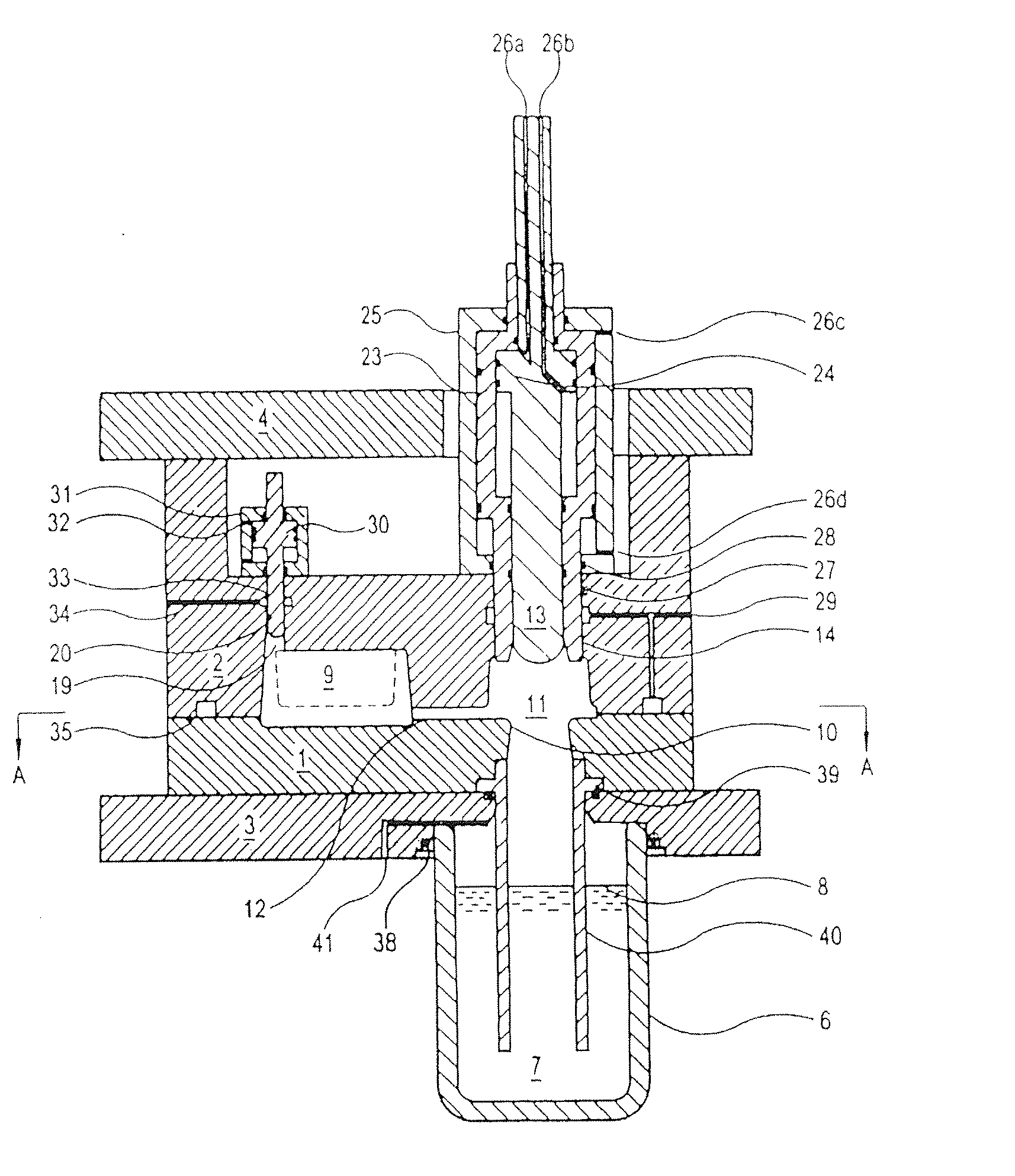
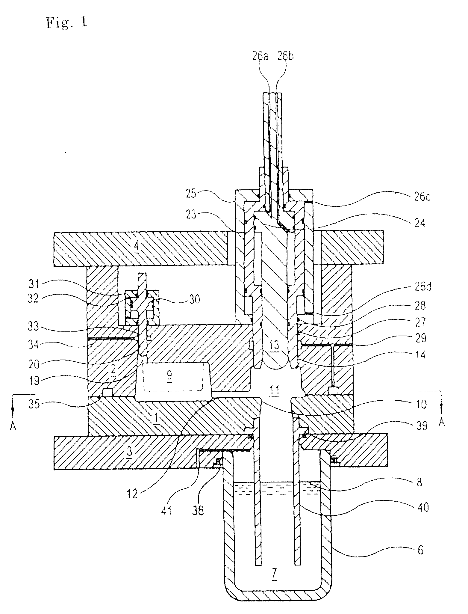
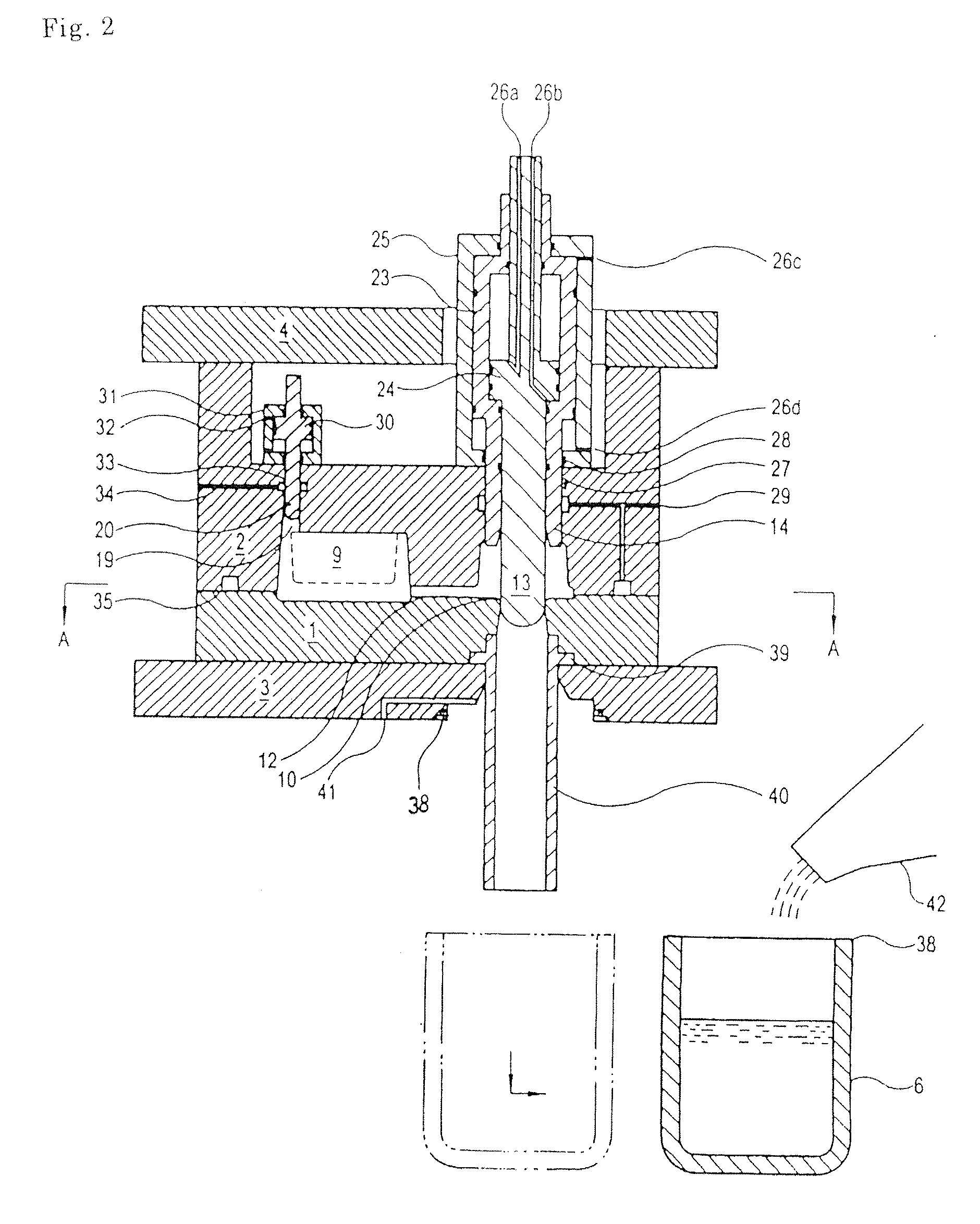
[0070] The vertical casting apparatus of the present invention is not particularly limited as long as it is a vertical casting apparatus including an apparatus body having a fixed mold on the lower side and a movable mold on the upper side, which can form a mold cavity; a closing means for closing a molten metal in-flow gate formed in the fixed mold; and a pressurizing means for pressurizing molten metal in the closed mold cavity, and a casting means for supplying and filling molten metal into the mold cavity from the underside, wherein the casting means has a gas-pressurized molten metal pouring ladle that is attachable to and detachable from the apparatus body. The vertical casting apparatus in accordance with the present invention is a vertical casting apparatus that has high work efficiency, ease of maintenance, and a low cost of equipment. Further, by using the vertical casting apparatus in accordance with the present invention, castings, especially thin-wall and large-size cas...


PUM

PropertyMeasurementUnit
Pressureaaaaaaaaaa
Sizeaaaaaaaaaa
Speedaaaaaaaaaa

Abstract

The present invention is to provide a vertical casting apparatus capable of easily manufacturing castings without causing shrinkage cavities and entrainment of gas, by filling a molten metal into a mold cavity at a high speed and by effectively pressurizing the molten metal in the closed cavity, which has high work efficiency, ease of maintenance, and a low cost of equipment, and a vertical casting method using the vertical casting apparatus. The vertical casting apparatus is provided with an apparatus body comprising a fixed mold 1 on the lower side and a movable mold 2 on the upper side, a closing means 13 for closing a molten metal in-flow gate 10 formed in the fixed mold 1, and a pressurizing means 20 for pressurizing the molten metal in the closed mold cavity, and a casting means for supplying and filling the molten metal into the mold cavity from the underside. The casting means has a gas-pressurized molten metal pouring ladle 6 attachable to and detachable from the apparatus body.

Description

TECHNICAL FIELD [0001] The present invention relates to a vertical casting apparatus capable of manufacturing castings such as aluminum alloys, in which a molten metal is filled into a mold cavity from underside, and, more particularly, to a vertical casting apparatus in which a molten metal is supplied and filled into a mold cavity from the underside by using a gas-pressurized molten metal pouring ladle, and a vertical casting method using the vertical casting apparatus. BACKGROUND ART [0002] In the case where castings such as light alloy products, especially parts requiring strength, are manufactured, a vertical casting apparatus are used to prevent entrainment of gas at the time when molten metal is poured. [0003] In such a vertical casting apparatus, as a means for supplying molten metal into a mold cavity from a molten metal holding furnace while preventing the mixing of oxides and the entrainment of gas, use of a low-pressure gas is already known (see Japanese Laid-Open Patent...

Claims


Application Information

Patent Timeline
IPC IPC(8): B22D18/04B22D27/13B22D18/00B22D17/06B22D15/00B22D18/06B22D27/09B22D27/11
CPCB22D15/005B22D27/11B22D18/04
Inventor MATSUBARA, NAGAYOSHIKOIDE, TAKASHIFUJINO, KIYOSHI
Owner KOSEI ALUMINUM
Why Eureka
Try Eureka