Air-oil heat exchanger

a technology of air-oil heat exchanger and lubricant, which is applied in the direction of indirect heat exchangers, machines/engines, lighting and heating apparatus, etc., can solve the problems of turbofan engine thrust loss, caused by heat loss of lubricant,

Active Publication Date: 2007-09-20
RAYTHEON TECH CORP
View PDF12 Cites 42 Cited by
  • Summary
  • Abstract
  • Description
  • Claims
  • Application Information

AI Technical Summary

Problems solved by technology

During such lubrications, heating of the lubricant is caused to occur due to mechanical energy losses in the lubricated apparatus.
Thus, such an air and lubricating oil heat exchanger duct based system continually leads to thrust losses in the turbofan engine despite being unnecessary for cooling the lubricating oil in many flight situations.

Method used


Image

  • Air-oil heat exchanger
  • Air-oil heat exchanger
  • Air-oil heat exchanger

Examples


Embodiment Construction

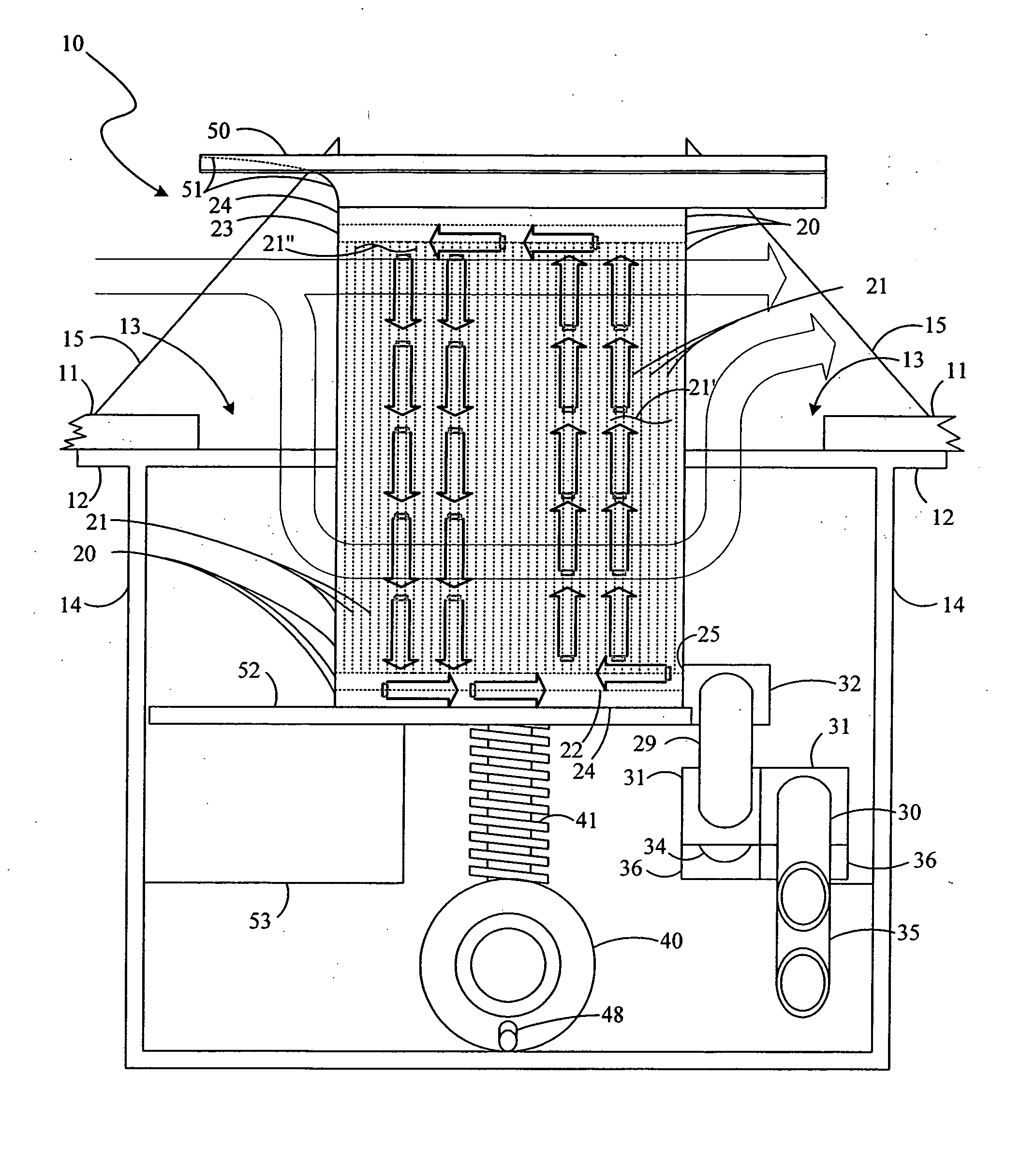
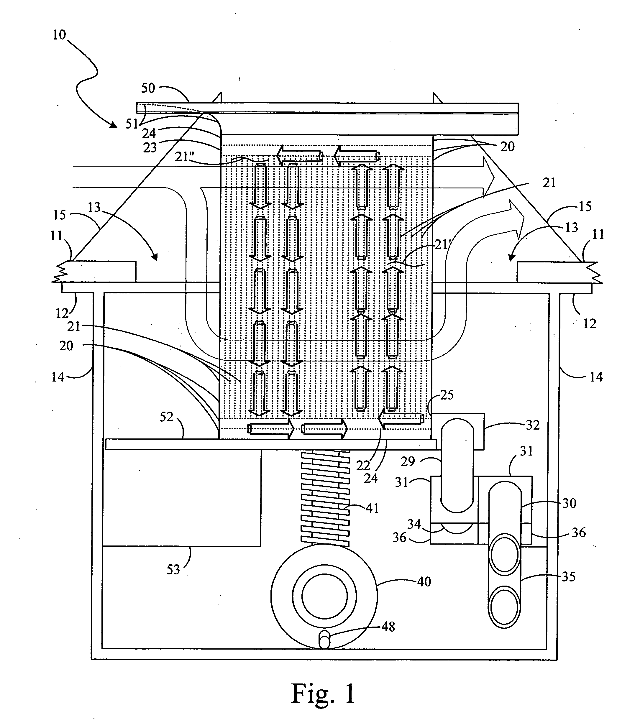
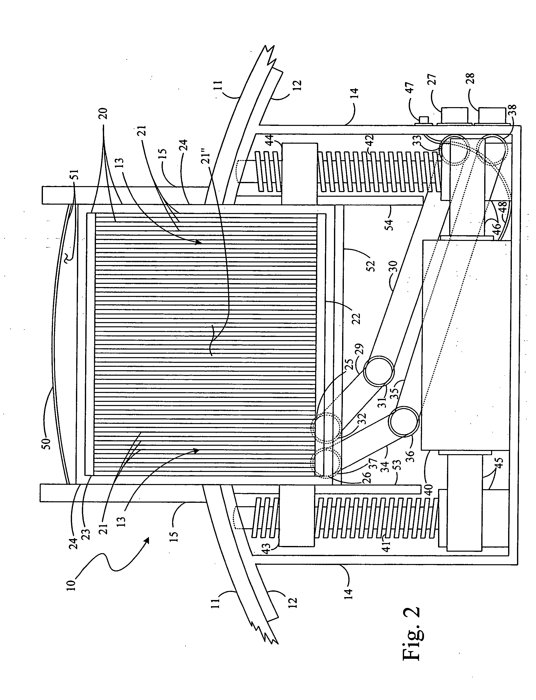
[0010]FIGS. 1 and 2 show partially cut away side and front views, respectively, of a partially deployed air-oil heat exchanger, 10, mounted on a portion of an inner fan duct wall, 11, provided in a turbofan engine which is otherwise omitted from this figure. A flange, 12, holds heat exchanger 10 against the inner engine core side of wall 11 so that the deployable portion of heat exchanger 10 can be deployed in the engine fan airstream through an opening, 13, in wall 11 that is on the opposite side of that wall from the engine core side thereof. Flange 12 is part of a metal container, 14, for heat exchanger 10 provided on the engine core side of wall 11.

[0011] A further bracket, 15, located primarily on the airstream side of wall 11 and fastened to container 14 through opening 13 holds that container against wall 11. Bracket 15 has triangular shaped sidewalls across from one another with an opening therebetween to the interior of container 14 below that bracket on the upstream side ...


PUM


Abstract

A heat exchange system for use in fluid operated equipment to provide air and working fluid heat exchanges to cool the working fluid in airstreams on a stream side of a wall. An actuator is mounted to be substantially located on a side of the wall opposite the stream side thereof having a positionable motion effector. A heat exchanger core having a plurality of passageway structures therein to enable providing the working fluid to, and removal therefrom. The heat exchanger core is mounted on the motion effector so as to be extendable and retractable thereby through the opening for selected distances into that region to be occupied by the airstreams.

Description

BACKGROUND OF THE INVENTION [0001] The present invention relates to lubrication systems for turbine engines and for associated equipment, and more particularly, to air and lubricant heat exchangers for use in maintaining desired temperatures of the lubricants in such engines and equipment. [0002] Lubrication systems for turbine engines, such as a turbofan engine, and for associated equipment, such as an integrated drive generator, provide pressurized lubricant, an oil, to lubricate, cool and clean the engine main bearings, gear box gears, and the like, and again for the lubrication of bearings and other parts in equipment associated with such turbine engines. During such lubrications, heating of the lubricant is caused to occur due to mechanical energy losses in the lubricated apparatus. Thermal management of such lubricants is very important for continued successful operation of such lubrication systems in the apparatus lubricated thereby. [0003] The amount of heat necessary to be ...

Claims


Application Information

Patent Timeline
Patent Type & Authority Applications(United States)
IPC IPC(8): F28F27/00
CPCF01D5/046F01D25/08F01D25/12F01D25/18F01D25/24F02C7/06F05D2260/232F02C7/14F02C7/16Y02T50/675F05D2260/211F05D2260/20F02C7/12F28D2021/0026F28D2021/0049F28F9/0246F28F2280/10Y02T50/60
Inventor SCHWARZ, FREDERICK M.ELSAESSER, FREDERICK L.
Owner RAYTHEON TECH CORP
Why Eureka
Try Eureka