
Conveyor belt scale system

Active Publication Date: 2007-09-20
MFR & TRADERS TRUST
View PDF24 Cites 18 Cited by
  • Summary
  • Abstract
  • Description
  • Claims
  • Application Information

AI Technical Summary

Benefits of technology

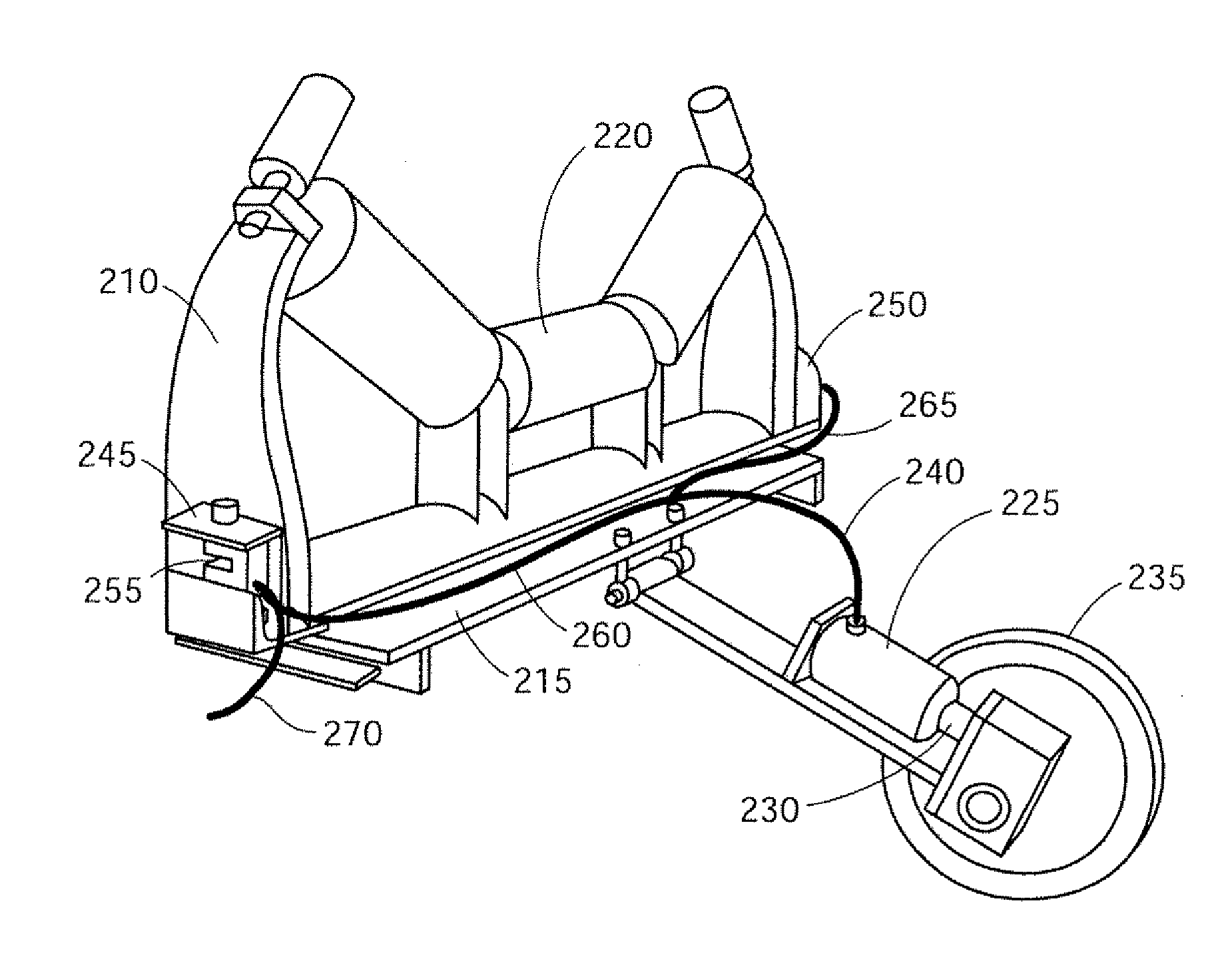
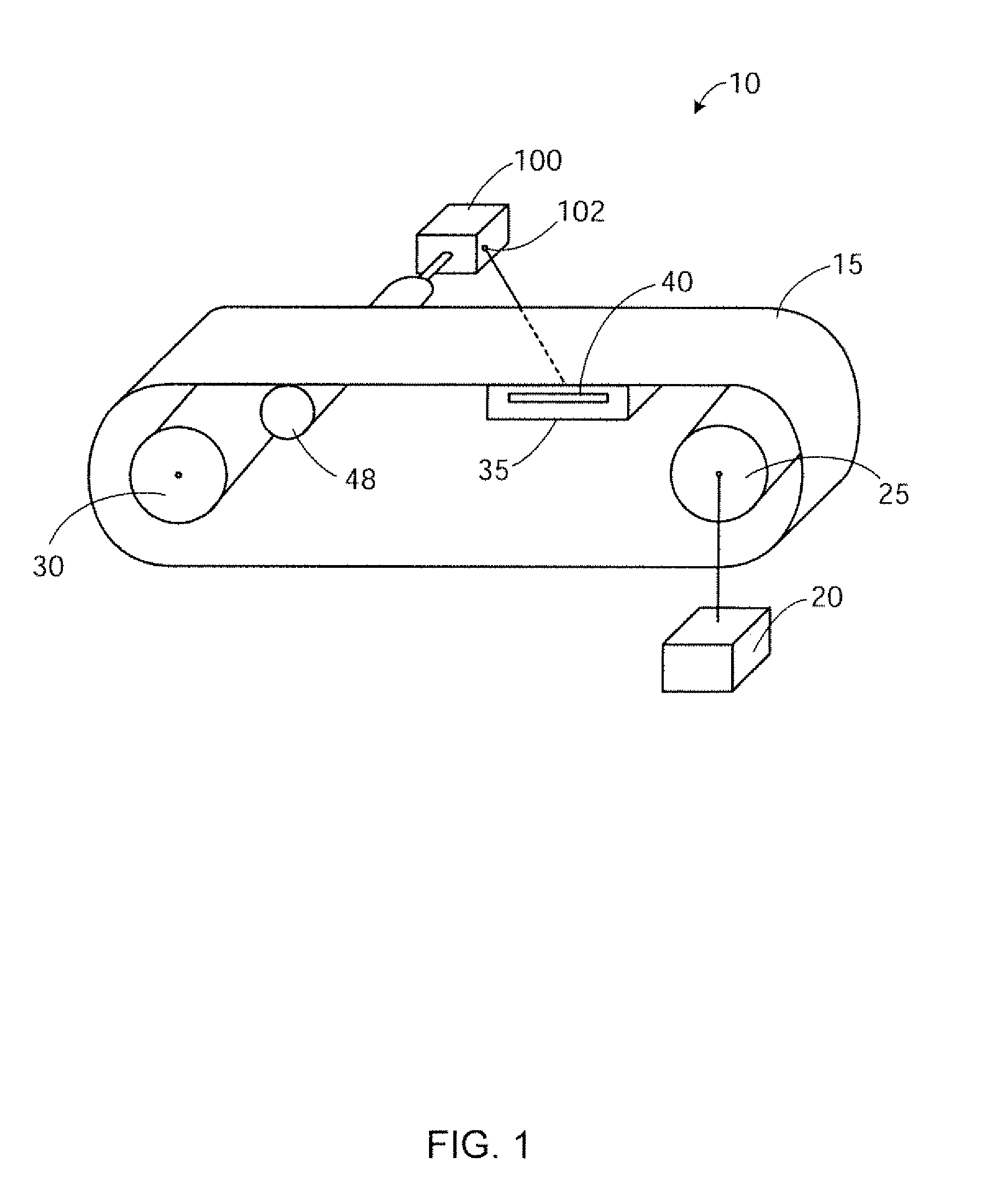
[0025] An embodiment may include a method of weighing material on a moving conveyor belt, A method may include placing a material that has a weight onto a conveyor belt. The conveyor belt may be moved at a desired speed. In an embodiment, a roller may be contacted with the moving conveyor belt, where the roller rotates in response to movement of the conveyor belt. Further embodiments may include outputting a generator voltage from a generator operably connected to the roller, wherein an amplitude of the generator voltage corresponds to the speed of the conveyor belt, and inputting the generator v

Problems solved by technology

In conventional belt scales, a single load cell is typically located below the belt such that when the belt stops moving and the forward forces cease to exist, the downward forces measured by the load cell increase, thereby causing inaccuracies in the actual weight measurements.
Relying on voltage and signal wires from the load cell and encoder makes the systems more susceptible to lightning strikes.

Method used


Image

  • Conveyor belt scale system
  • Conveyor belt scale system
  • Conveyor belt scale system

Examples


Embodiment Construction

[0036] Before the present methods, systems and materials are described, it is to be understood that this disclosure is not limited to the particular methodologies, systems and materials described, as these may vary. It is also to be understood that the terminology used in the description is for the purpose of describing the particular versions or embodiments only, and is not intended to limit the scope.

[0037] It must also be noted that as used herein and in the appended claims, the singular forms “a,”“an,” and “the” include plural references unless the context clearly dictates otherwise. Unless defined otherwise, all technical and scientific terms used herein have the same meanings as commonly understood by one of ordinary skill in the art. Although any methods, materials, and devices similar or equivalent to those described herein can be used in the practice or testing of embodiments, the preferred methods, materials, and devices are now described. All publications mentioned herei...


PUM


Abstract

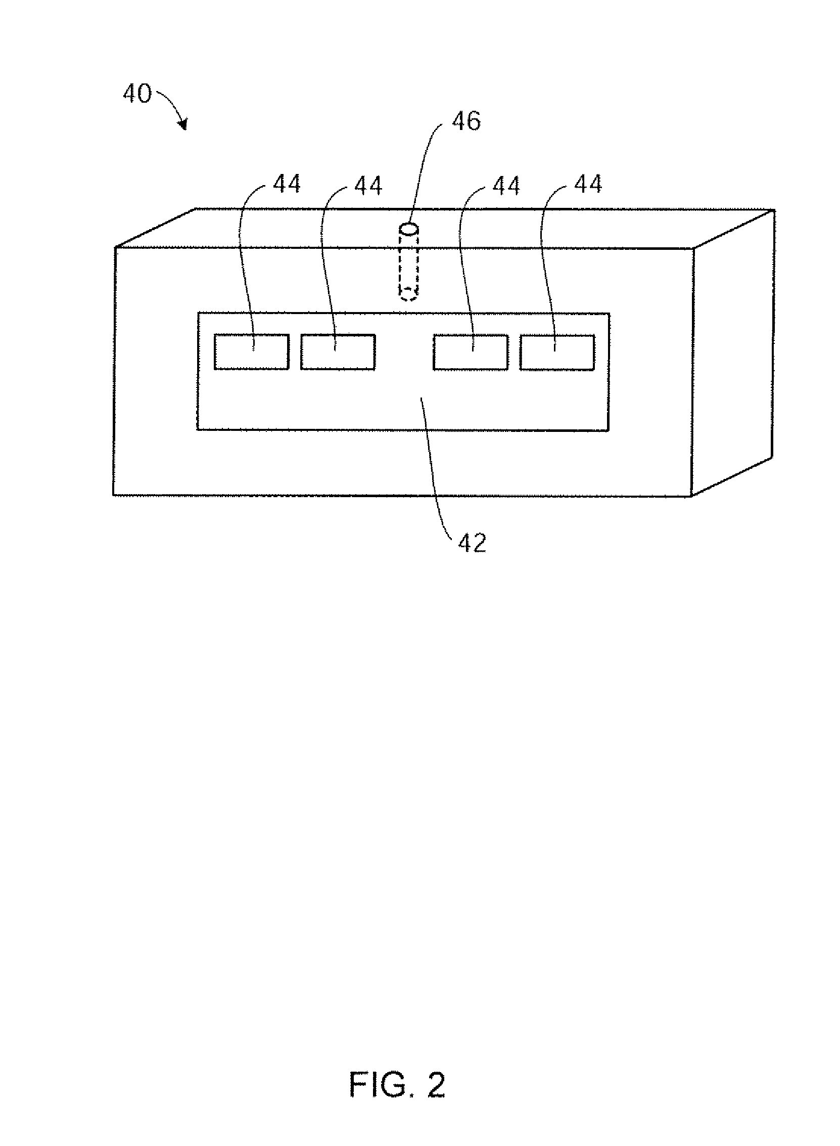
A scale may include a conveyor belt that carries a load, where the load has a weight. A generator is included that receives mechanical energy arising from movement of the conveyor belt and outputs electrical energy that corresponds to a rate of movement of the conveyor belt. At least one load cell receives the electrical energy from the generator, senses the weight of the load, and outputs a voltage that corresponds to the weight of the load and the rate of movement of the conveyor belt.

Description

CROSS-REFERENCE TO RELATED APPLICATIONS [0001] This patent application claims priority to co-pending U.S. provisional patent application No. 60 / 775,058, filed on Feb. 21, 2006, entitled “Conveyor Belt Scale System”, the disclosure of which is incorporated herein by reference in its entirety.STATEMENT REGARDING FEDERALLY SPONSORED RESEARCH [0002] Not applicable. NAMES OF PAR TIES TO A JOINT RESEARCH AGREEMENT [0003] Not applicable. SEQUENCE LISTING [0004] Not applicable. BACKGROUND [0005] 1. Technical Field [0006] The disclosed embodiments generally relate to the field of conveyor belt weighing systems. More particularly, the description generally relates to generators as a means for providing excitation voltage for conveyor belt scales, and methods for using generators with conveyor belt scales. [0007] 2. Description of the Related Art [0008] It is often desirable to measure and / or control the mass flow rate of material such as aggregate moving on a conveyor belt. By combining the w...

Claims


Application Information

Patent Timeline
IPC IPC(8): G01G9/00G01G11/14G01G7/04
CPCB65G15/00G01G23/3728G01G11/14G01G11/04
Inventor WINELAND, GARY
Owner MFR & TRADERS TRUST
Learn More