Brake Disk, Especially for a Rail Vehicle

a brake disk and rail vehicle technology, applied in the direction of brake types, braking elements, mechanical devices, etc., can solve the problems of insufficient high-performance, insufficient centering of the hub of the axle-mounted brake disk, and inability to adjust the rotational angle of the brake disk, so as to ensure the overall safety of the form fitting, high dynamic loading, and high redundancy

Inactive Publication Date: 2007-09-20
KNORR BREMSE SYST FUR SCHIENENFAHRZEUGE GMBH
View PDF7 Cites 13 Cited by
  • Summary
  • Abstract
  • Description
  • Claims
  • Application Information

AI Technical Summary

Benefits of technology

[0023] A form fit between the sliding elements and the radial grooves which can be subjected to high dynamic loading is obtained when the sliding elements, or the guide pins, are of planar design in the region bearing against the side wall of the radial grooves. Contact seating of the friction ring on the hub can thus be dispensed with, with the effect that removal without any problems is possible even in the case of a shrunken friction ring.
[0024] Due to the high redundancy which results from the relatively large number of form-fit connections, increased safety of the form fit overall is ensured. That turns out to be an advantage in the event of a possible incorrect assembly.
[0025] The small space required for accommodating the sliding elements on the one hand, and for incorporating the radial grooves on the other hand, permits the use of these form-fit connections in virtually all types of disk construction.

Problems solved by technology

Since the friction rings expand due to the heating which occurs during the braking, simple centering by cylindrical seating on the hubs of axle-mounted brake disks, in particular in the case of two-piece high-performance brake disks, does not suffice.
The sliding blocks therefore prevent a radial displacement of the respective friction ring from occurring due to the applied braking torque or due to dynamic shocks, thereby possibly resulting inunacceptable unbalance.
In addition, friction rings made of ductile materials, for example steel, may shrink during operation due to plasticization processes in the friction surfaces, caused by high braking power and high temperatures.
However, the realization of these connections is only possible at a relatively high production cost, which precludes optimized manufacture from the cost point of view.
Furthermore, only a very small number of sliding blocks are used, normally three to six, which are dimensioned to be correspondingly large on account of the requisite load absorption and therefore take up a large amount of space.
An additional drawback is non-uniform load transmission together with the resulting stresses due to the known arrangement and design of the sliding blocks.
This value appears to be small, but in the case of friction ring masses of about 100 kg (average size) means unbalance of U=m·e=4 gm (e=eccentricity).
This value already amounts to more than half the acceptable unbalance in the case of high-performance brake disks.
As already mentioned, it is very costly to make the radial grooves and the sliding blocks, especially by the requisite machining.

Method used


Image

  • Brake Disk, Especially for a Rail Vehicle
  • Brake Disk, Especially for a Rail Vehicle
  • Brake Disk, Especially for a Rail Vehicle

Examples


Embodiment Construction

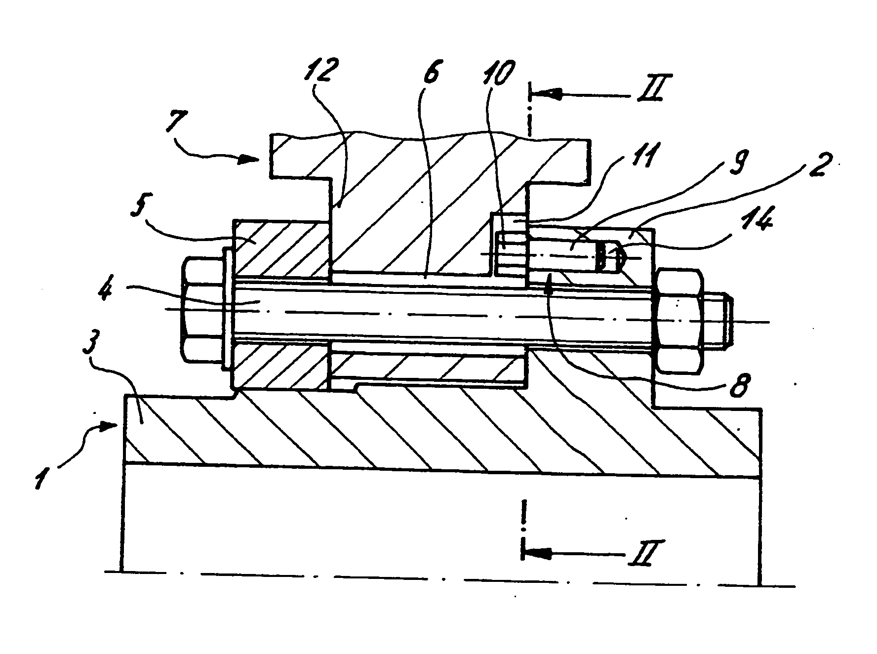
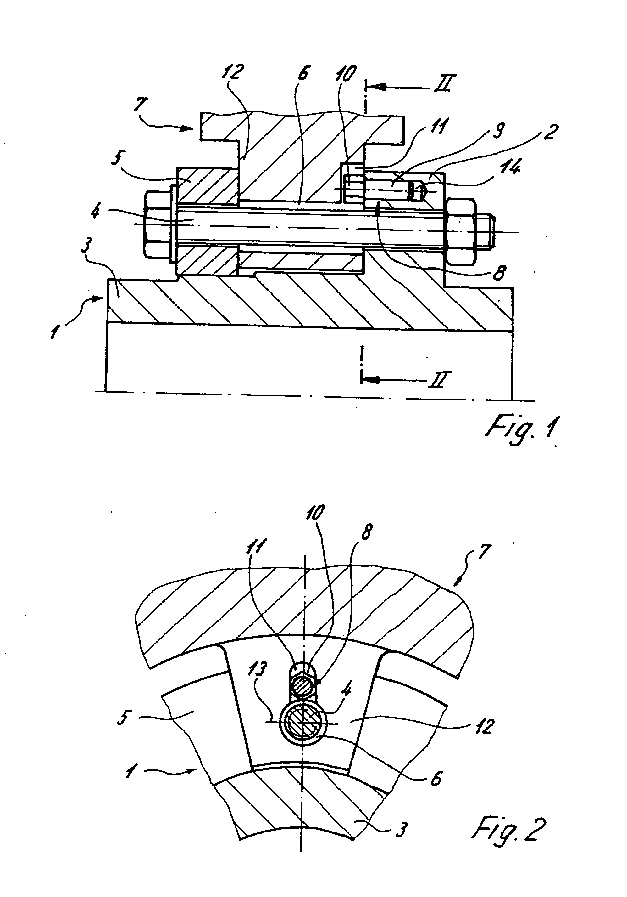
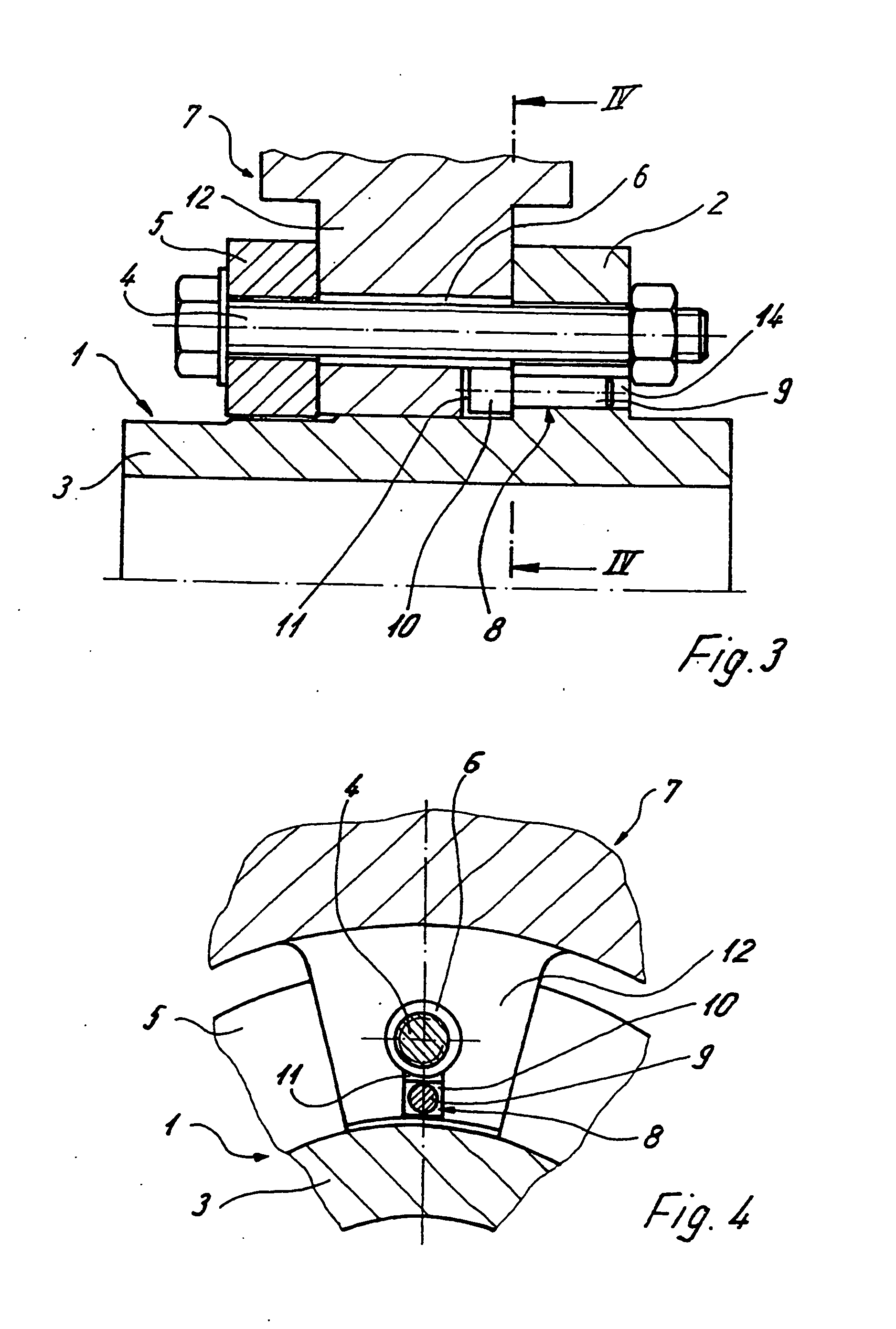
[0034] Shown in FIGS. 1 to 6 are illustrative embodiments of an axle-mounted brake disk, which embodiments include a hub 1 having an axially extending hub body 3 and an encircling hub flange 2 extending radially thereto. Also included is at least one friction ring 7 which is fastened to the hub 1 by clamping bolts 4.

[0035] The clamping bolts 4 are passed through a clamping ring 5 arranged opposite the hub flange 2, through a connecting lug or flange 12 assigned to each clamping bolt 4 of the friction ring 7 and through the hub flange 2. The connecting flange 12 includes a through-hole 6 for passing the clamping bolt 4 through and clamping the clamping bolt 4 in place between the clamping ring 5 and the hub flange 2.

[0036] A radial groove 11 is provided in the connecting flange 12 in the region of each through-hole 6. Radial groove 11, as shown in FIG. 1, extends outward toward a center longitudinal axis of the hub starting from the through-hole 6 relative to a pitch circle diamete...


PUM


Abstract

A brake disk for a rail vehicle includes a hub and at least one friction ring having radial grooves. The friction disk is fastened by a clamping bolt to the hub. Also included are sliding elements having a shank and the sliding elements are connected to the hub. The sliding elements engage in the radial grooves for anti-rotation locking and centering of the at least one friction ring. The sliding elements extend parallel to an axis of the clamping bolt.

Description

BACKGROUND AND SUMMARY [0001] The present disclosure relates to a brake disk for a rail vehicle. The brake disk includes at least one friction ring which is provided with radial grooves and is fastened by clamping bolts to a hub, which can be secured to a shaft or a wheel disk. Sliding elements are connected to the hub or the wheel disk and engage in the radial grooves for anti-rotation locking and centering of the friction ring. [0002] Such brake disks, which are used as “axle-mounted or wheel-mounted brake disks”, are subjected during operation to considerable mechanical and thermal stresses, which require special design measures in order to firstly ensure the requisite safety and secondly permit reasonably practicable assembly and dismantling for exchange purposes. [0003] Since the friction rings expand due to the heating which occurs during the braking, simple centering by cylindrical seating on the hubs of axle-mounted brake disks, in particular in the case of two-piece high-pe...

Claims


Application Information

Patent Timeline
Patent Type & Authority Applications(United States)
IPC IPC(8): F16D65/12
CPCF16D65/123F16D2065/136F16D2065/1392F16D2065/1384F16D2065/138
Inventor WIRTH, XAVERMOSBACH, CHRISTIAN
Owner KNORR BREMSE SYST FUR SCHIENENFAHRZEUGE GMBH
Why Eureka
Try Eureka