Eureka AIR delivers breakthrough ideas for toughest innovation challenges, trusted by R&D personnel around the world.

Heald shaft

Inactive Publication Date: 2007-01-11
GROZ BECKERT KG
View PDF22 Cites 5 Cited by
  • Summary
  • Abstract
  • Description
  • Claims
  • Application Information

AI Technical Summary

Benefits of technology

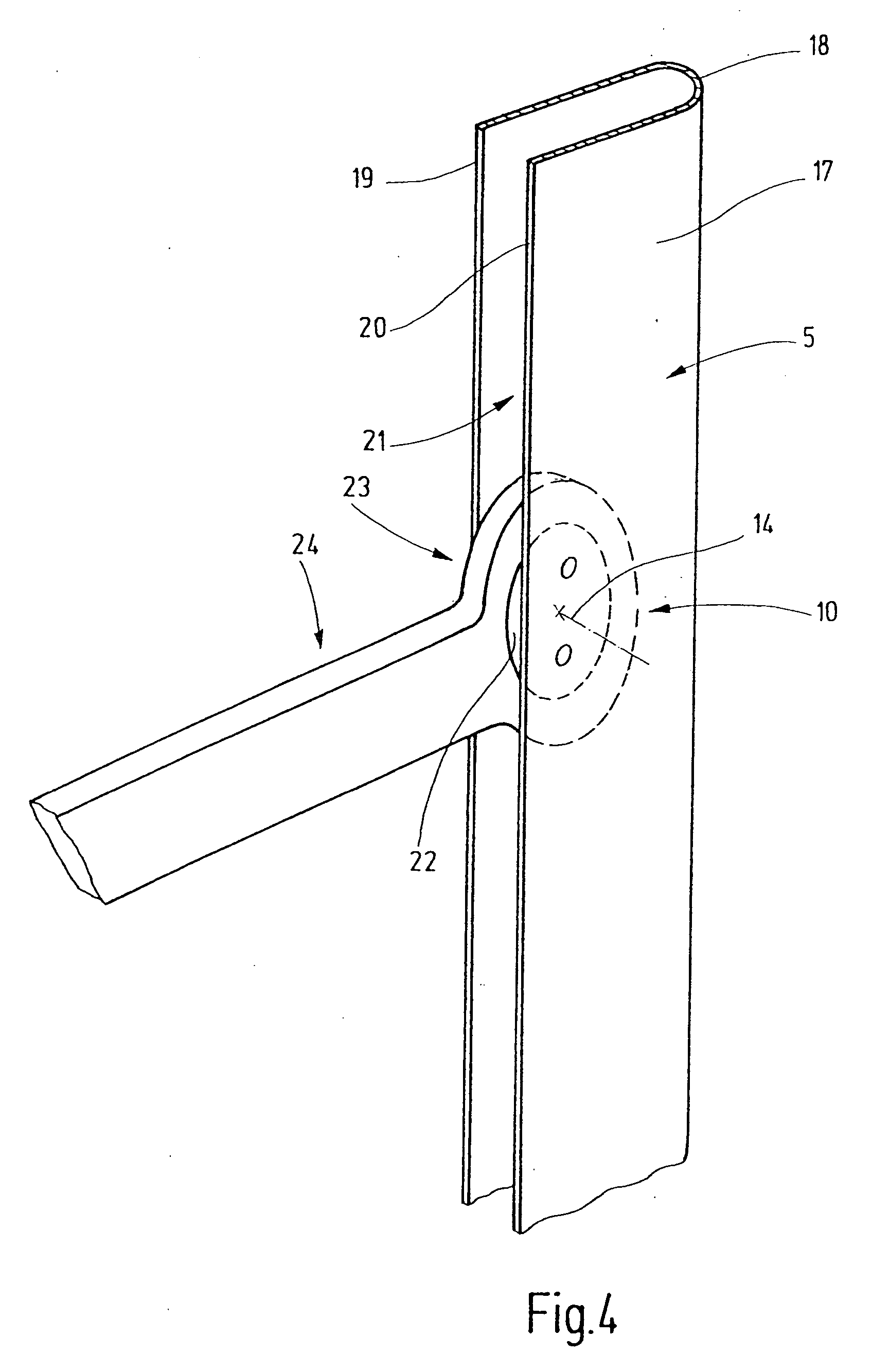
[0014] The combination of the features, according to which the structure is free from resetting forces and the pivotal axis is situated externally of the shaft rod, results in the possibility to impart high dynamic loads to the heald shaft without adversely affecting the end binders and to reduce the load thereon.
[0015] Further, as defined in claim 2, it is advantageous to provide, at the end binder, a driving coupler which introduces a force whose direction or vector lies within the end binder. Here too, the pivot axis of the connecting joint lies externally of the shaft rod. In this manner dynamic loads, which may be generated by the introduction of driving forces into the end binder, as well as dynamic loads which may appear because of the transmission of driving forces from the end binder to the shaft rod are reduced. The end binders are thus essentially exposed to traction and pressure, but to essentially no bending, making feasible a relatively light-weight structure of the end binders.
[0017] The connecting joint comprises a bearing body which is preferably attached to the end binder and whose outer surface then constitutes a slide surface or bearing surface. The bearing body may be entirely disposed in the inner space of the end binder. In case the bearing body has a slightly larger diameter, it is, however, preferable for allowing it to project from the inner space of the end binder. Such an arrangement minimizes dynamic surface loads on the bearing body.

Problems solved by technology

As a result, such acceleration forces cannot generate appreciable bending moments in the end binder.

Method used


Image

  • Heald shaft
  • Heald shaft
  • Heald shaft

Examples


Embodiment Construction

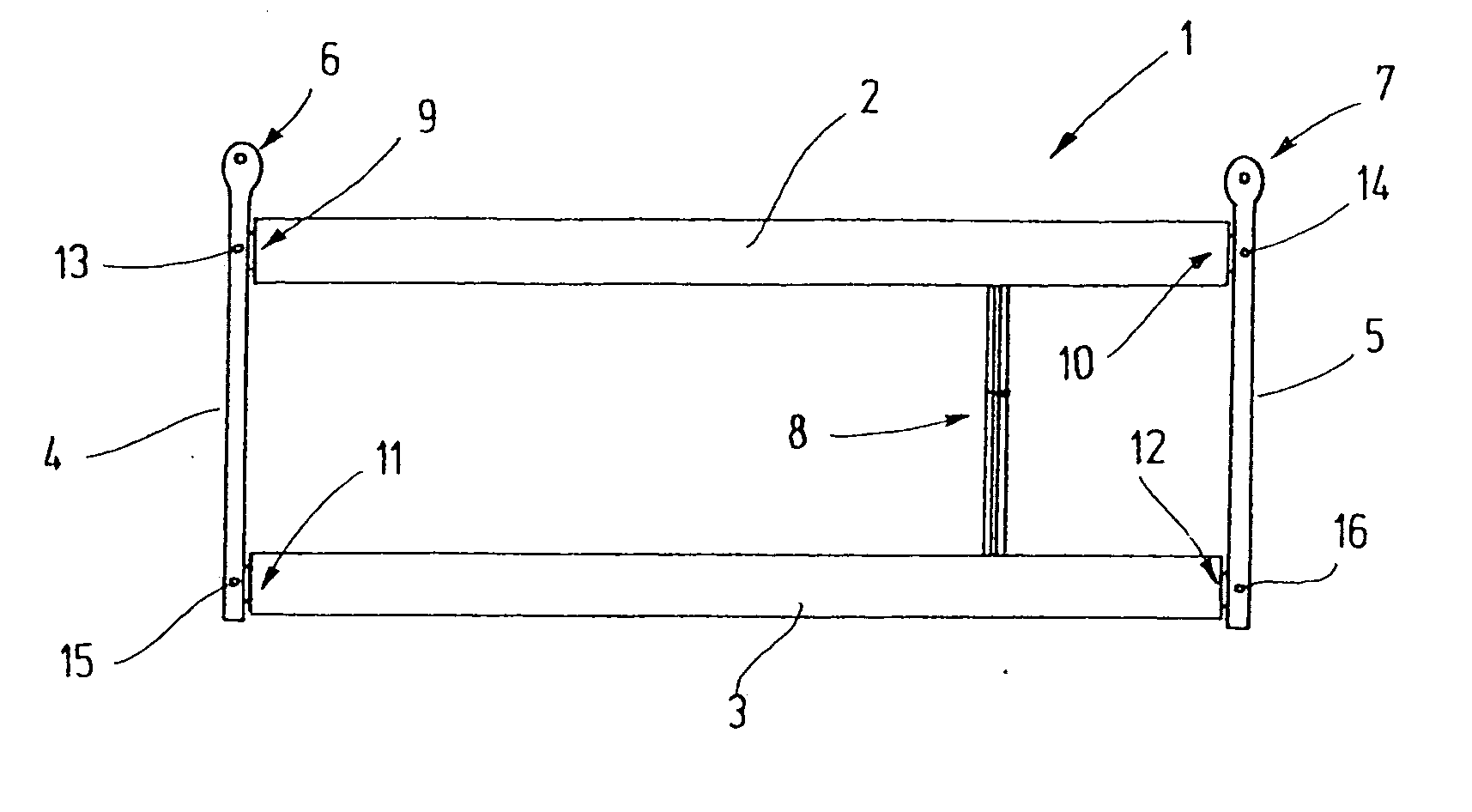
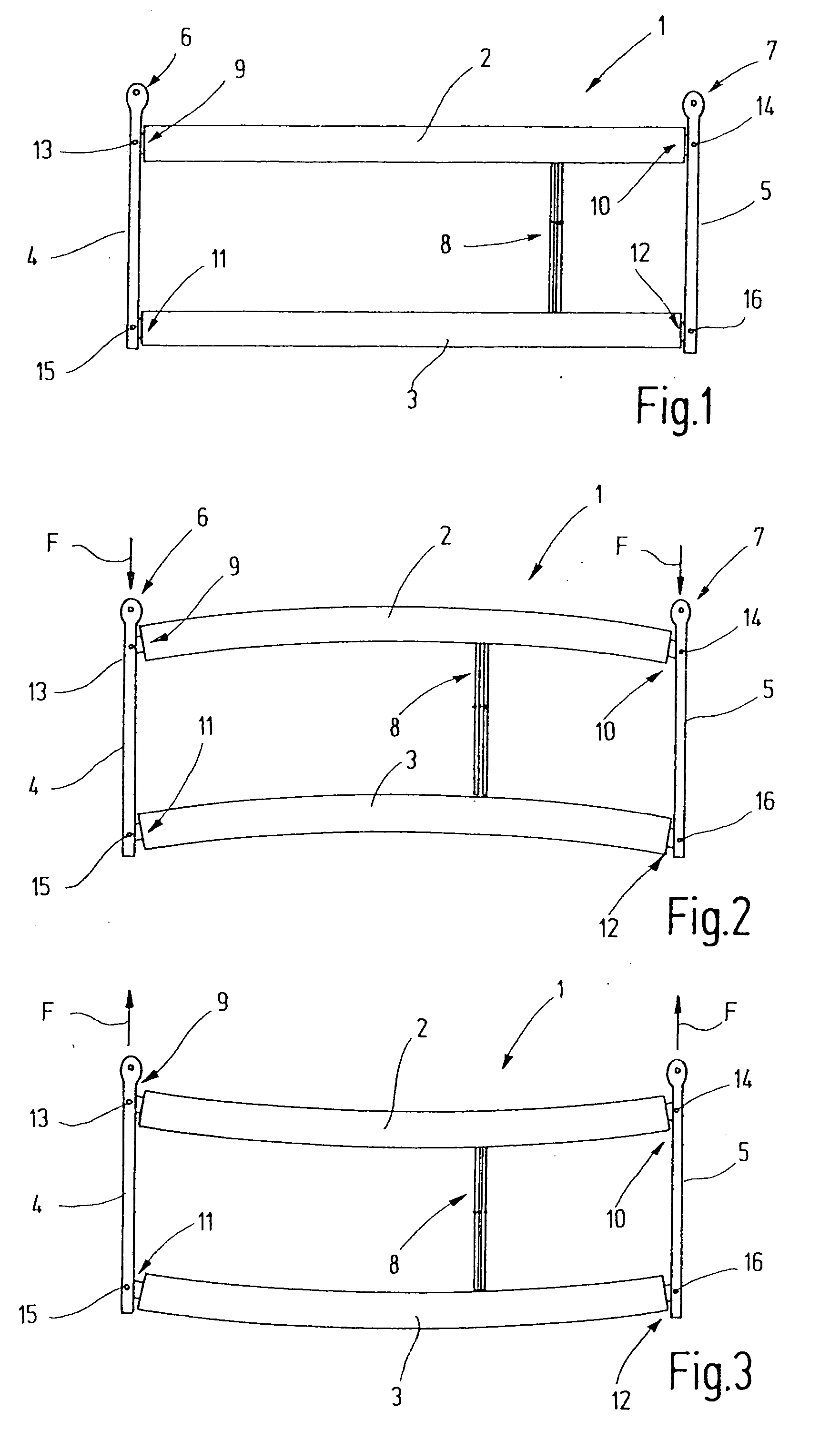
[0029]FIG. 1 illustrates a heald shaft 1 which serves for the shed formation in a textile machine. The heald shaft 1 comprises upper and lower shaft rods 2, 3 which are extruded, hollow-chamber aluminum profiles and which are oriented horizontally and parallel to one another. At their ends the shaft rods 2 and 3 are interconnected by end binders 4, 5 which, for example, at their upper end, are connected with driving couplers 6, 7. The latter form part of a coupling device for establishing a connection with a mechanical drive.

[0030] The shaft rods 2, 3 are provided with shaft staves which support healds 8 for guiding the warp threads. FIG. 1 shows merely a few healds; the heald group, however, extends from one end of the shaft rods 2, 3 to the respective other end thereof.

[0031] For connecting the shaft rods 2, 3 with the end binders 4, 5, connecting joints 9, 10, 11, 12 are provided which establish, between the respective shaft rod 2, 3 and the end binder 4, 5, a jointed connectio...


PUM


Abstract

The heald shaft (1) according to the invention has, for coupling the shaft rods (2) with the end binders (5), connecting joints (10) whose pivot axes (14) lie externally of the shaft rods (2) and preferably inside the end binders (5). By means of the connecting joints (10) a moment-free coupling between the shaft rods (2) and the end binders (5) is ensured. The relative pivotal motions between the shaft rods (2) and the end binders (5) appearing during operation do not generate any moment transmissions between the shaft rods (2) and the end binders (5). According to a preferred embodiment, the driving couplers (7) are arranged above the end binders (5) in a direct extension thereof.

Description

CROSS REFERENCE TO RELATED APPLICATION [0001] This application claims the priority of German Patent Application No. 10 2005 029 699.8-26, filed on Jun. 24, 2005, the subject matter of which, in its entirety, is incorporated herein by reference. BACKGROUND OF THE INVENTION [0002] The invention relates to a heald shaft having shaft rods and end binders. [0003] As rule, heald shafts comprise two spaced, mutually parallel held shaft rods which, at their ends, are connected to one another by end binders. In the position of rest, the end binders and the shaft rods form a rectangular frame. The shaft rods are provided with shaft staves which support healds. Each heald has at least one yarn-guiding eyelet through which a warp yarn passes. [0004] During the weaving process, the heald shafts are, for shed-building, rapidly reciprocated vertically, whereby large dynamic loads are generated. [0005] U.S. Pat. No. 4,022,252 describes a heald shaft having a rigid connection between the two vertica...

Claims


Application Information

Patent Timeline
IPC IPC(8): D03D41/00
CPCD03C9/065D03C9/0683D03C9/0675
Inventor DROPE, STEFANBRUSKE, JOHANNESGESING, KARL-HEINZ
Owner GROZ BECKERT KG
Why Eureka
Eureka Blog
Learn More