Removable nozzle-cooling mechanism

a cooling mechanism and nozzle technology, applied in the field of welding torch, can solve the problems of affecting the welding operation, and generally not including a cooling mechanism in the assembly in use, and achieve the effect of facilitating the adjustment of the aperture siz

Inactive Publication Date: 2007-09-20
ILLINOIS TOOL WORKS INC
View PDF13 Cites 12 Cited by
  • Summary
  • Abstract
  • Description
  • Claims
  • Application Information

AI Technical Summary

Benefits of technology

[0008] In accordance with certain embodiments, the present technique provides a cooling collar for the cooling of a welding torch nozzle. The exemplary cooling collar is a hollow structure that has an inner peripheral surface and an outer peripheral surface, the inner peripheral surface at least partially defining an aperture for

Problems solved by technology

Unfortunately, weld splatter, which is a polluting byproduct of the welding operation, better adheres to heated nozzle surfaces, interfering with the flow of shielding material.
Unfortunately, most welding torch assemblies in use generally do not include a mechanism for cooling the nozzle to prevent or reduce the accumulation of weld splatter.
These cleanings can be time-consuming and, often, lead to unwanted downtime and delays in the welding operation.
Moreover, if the operator delays or forgets the cleaning, gas flow

Method used


Image

  • Removable nozzle-cooling mechanism
  • Removable nozzle-cooling mechanism
  • Removable nozzle-cooling mechanism

Examples


Embodiment Construction

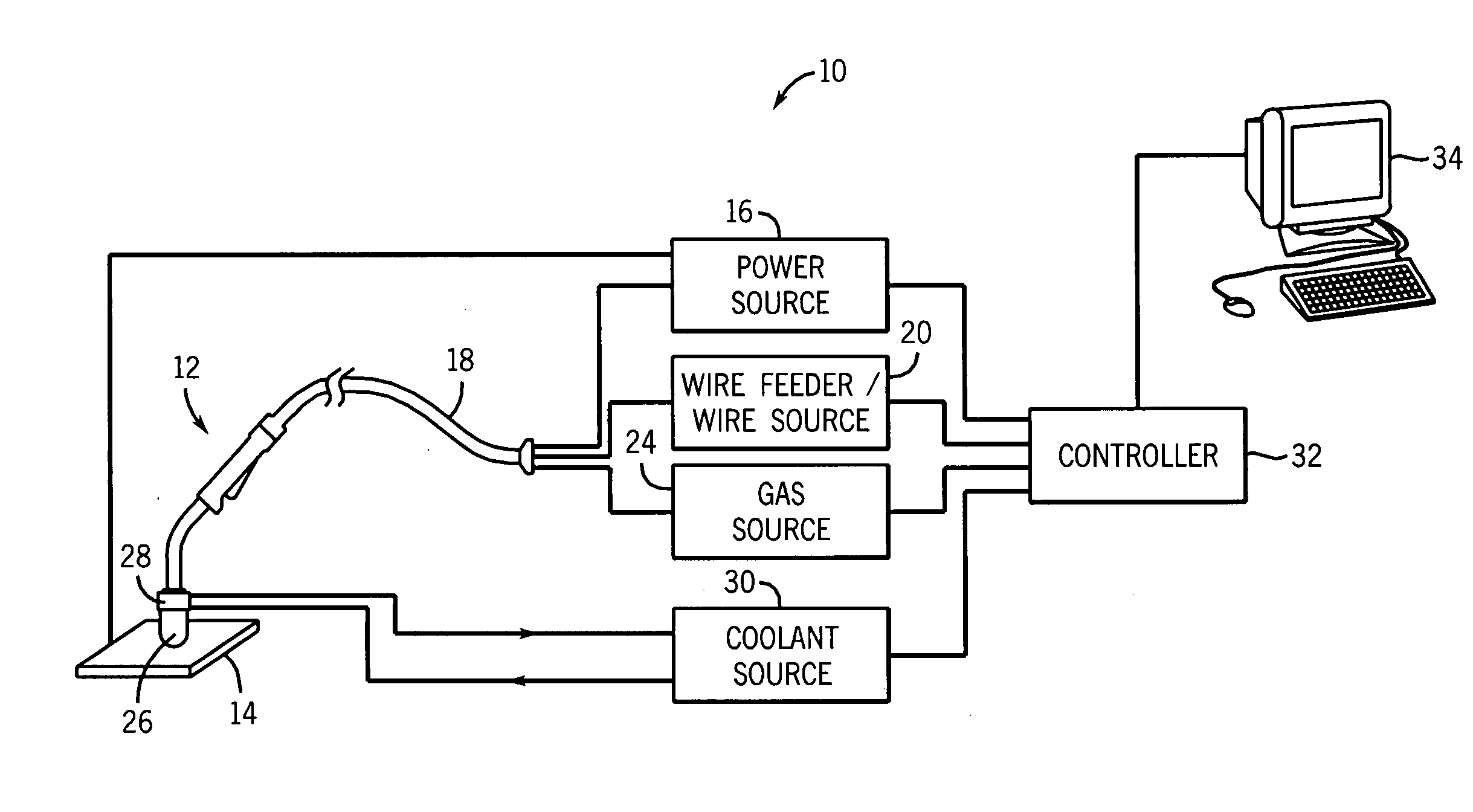
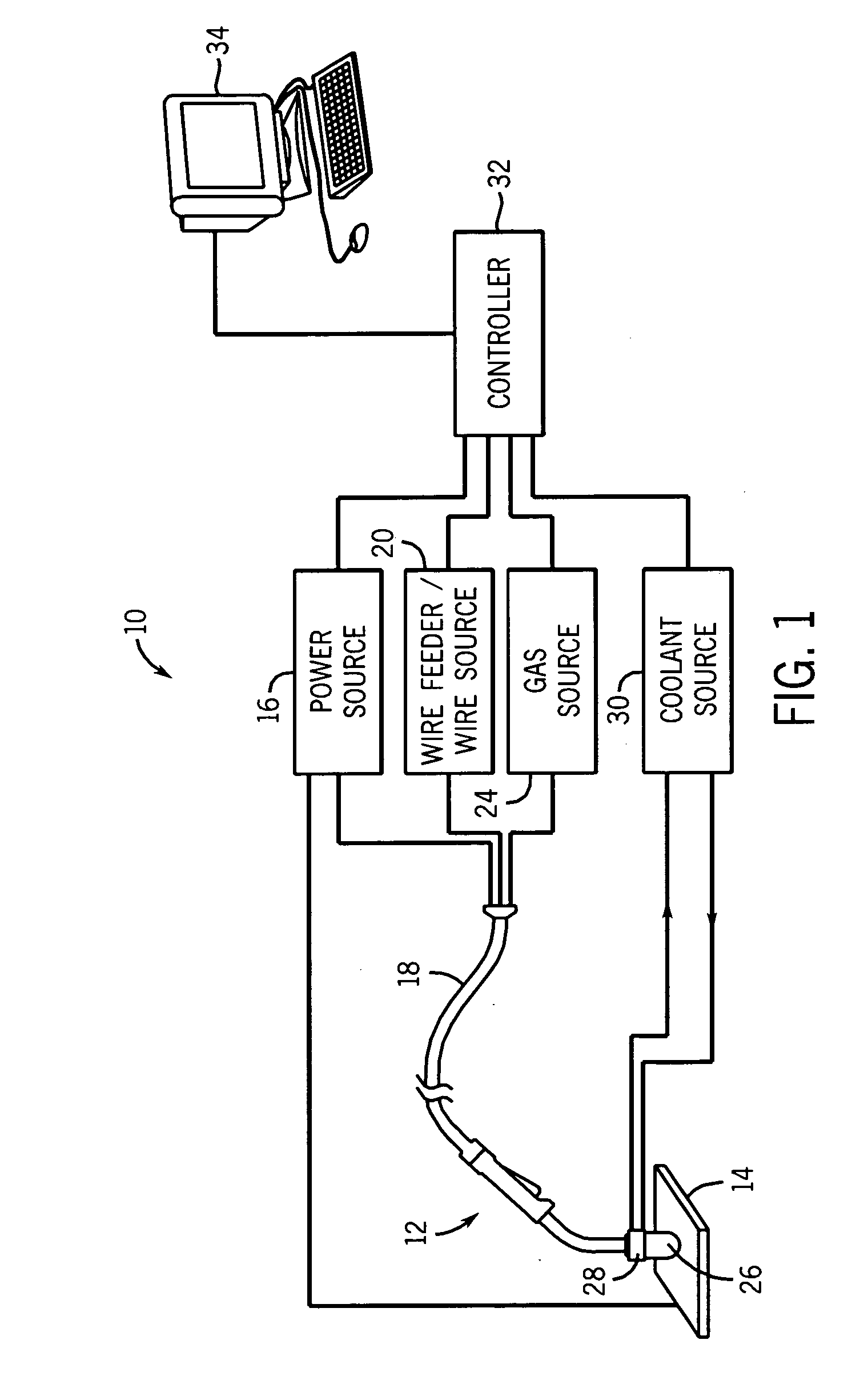
[0018] Turing to the drawings, FIG. 1 illustrates an exemplary gas-shielded wire-feed welding system 10. Prior to continuing, however, it is worth noting that the following discussion merely relates to exemplary embodiments of the present technique. As such, the appended claims should not be viewed as limited to those embodiments discussed herein. Indeed, the present invention provides benefits to any number of devices in which nozzle cooling is a concern.

[0019] Returning to the exemplary welding system 10, it includes a welding torch 12 that defines the location of the welding operation with respect to a workpiece 14. Placement of the welding torch 12, whether manually or mechanically, at a location proximate to the workpiece 14 allows current, which is provided by a power source 16 and which is routed to the welding torch via a welding cable 18, to arc from the welding torch 12 to the workpiece 14. In summary, this arcing completes a circuit from the power source 16, to the weldi...


PUM

PropertyMeasurementUnit
Sizeaaaaaaaaaa
Electrical conductoraaaaaaaaaa
Metallic bondaaaaaaaaaa

Abstract

A removable cooling collar is provided for cooling the nozzle of a welding nozzle. This collar includes first and second parts in fluid communication with a chamber that extends circumferentially within a hollow structure. Cooling fluid circulating through the chamber facilitates dissipation and/or extraction of heat in the nozzle, in turn reducing the likelihood of weld splatter adhesion on the nozzle.

Description

BACKGROUND [0001] The present invention relates generally to welding torches and, particularly, to a removable nozzle-cooling device for welding torches. [0002] A common metal welding technique employs the heat generated by electrical arcing to transition one or more workpieces to a molten state, thereby facilitating the weld. One technique that employs this arcing principle is wire-feed welding. At its essence, wire-feed welding involves routing current from a power source and into an electrode that is brought into close proximity with the workpiece. When close enough, current arcs from the electrode to the workpiece, completing a circuit and generating sufficient heat to transition the workpiece to a molten state, effectuating welding of the workpiece. [0003] To prevent the ingress of impurities into the molten weld and to improve the weld, a flow of shielding material is often provided about the weld location. For example, inert shielding gas from a gas source can be routed throu...

Claims


Application Information

Patent Timeline
IPC IPC(8): B23K9/12
CPCB23K9/295B23K9/285
Inventor CENTNER, ROBERT J.
Owner ILLINOIS TOOL WORKS INC
Why Eureka
Try Eureka