Liquid material placing method, manufacturing method for electro-optical device, electro-optical device and electronic apparatus

a manufacturing method and liquid material technology, applied in lighting and heating apparatus, combustion types, instruments, etc., can solve the problems of long drawing time and irregular amount of liquid material placed, and achieve the effect of high efficiency of using nozzles

Inactive Publication Date: 2007-09-20
SEIKO EPSON CORP
View PDF6 Cites 0 Cited by
  • Summary
  • Abstract
  • Description
  • Claims
  • Application Information

AI Technical Summary

Benefits of technology

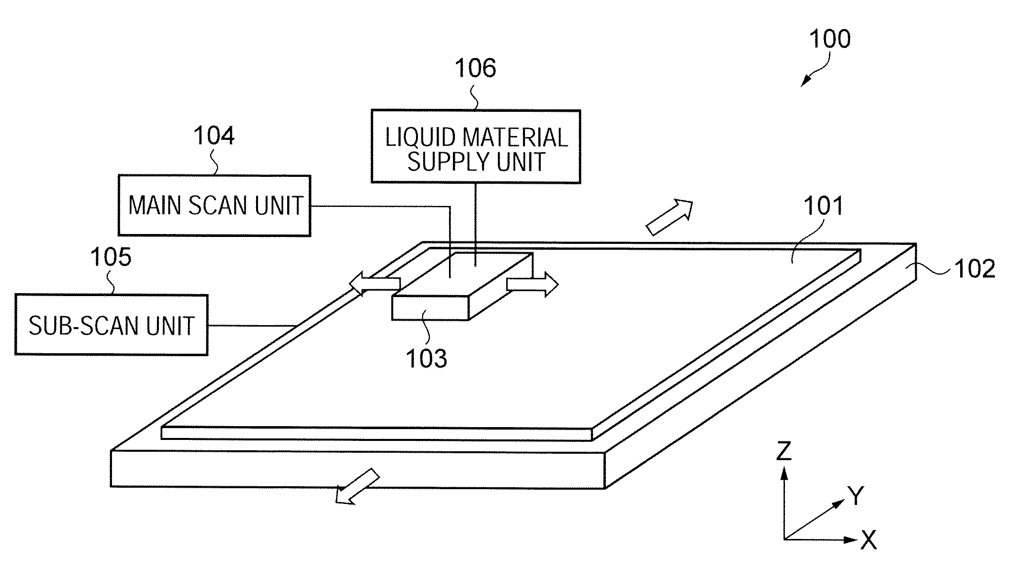
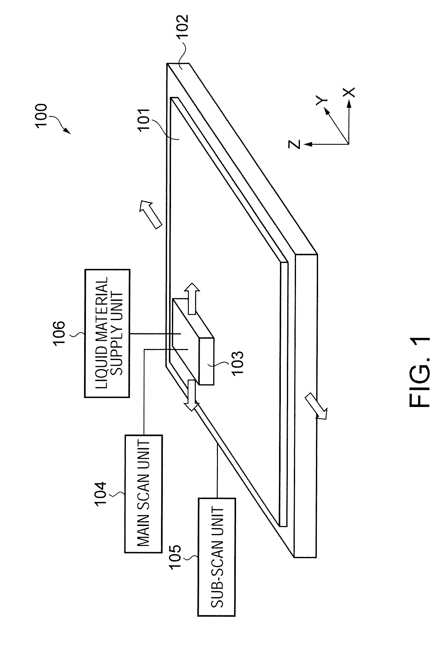
[0015]An advantage of the invention is to provide a liquid material placing method that allows placing a liquid material with slight irregularity in high efficiency of using nozzles, a method for manufacturing an electro-optical device using the liquid material placing method, and an electro-optical device and an electronic apparatus manufactured by this manufacturing method.
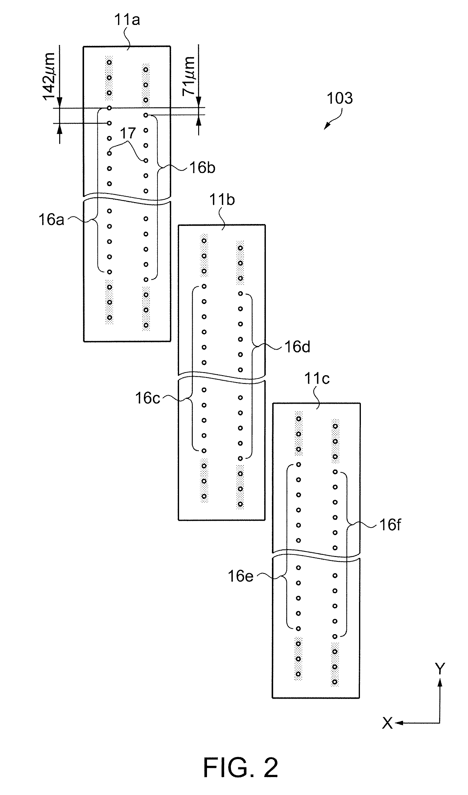
[0016]A method for placing a liquid material according to one aspect of the invention includes a) discharging the liquid material from a plurality of nozzles into a single region of a substrate during a scan of the substrate performed by a head having a nozzle group including the plurality of nozzles using a first electric pulse, and b) discharging the liquid material into the single region from the plurality of nozzles during the scan using a second electric pulse.
[0017]The first and second electric pulses are supplied to a pressure controller to control pressure of a liquid chamber communicated with the plurality of nozzles so as to cause the plurality of nozzles to discharge the liquid material.
[0018]The first and second discharge steps are performed by using the same plurality of nozzles during the same scan.
[0019]Preferably, a distribution width of discharge amounts in the nozzle group in a discharge using the first electric pulse is defined as a1, a distribution width of discharge amounts in the nozzle group in a discharge using the second electric pulse is defined as a2, and a distribution width of total discharge amounts in the nozzle group in a discharge using both the first and second electric pulses is defined as b, then a1, a2 and b satisfy a relationship: b<a1+a2.
[0020]According to the method for placing a liquid material according to one aspect of the invention, a droplet (liquid material) discharged by the first electric pulse and a droplet (liquid material) discharged by the second electric pulse are placed into a single partition region by the same scan.

Problems solved by technology

The variations cause a problem of irregularity in amount of the placed liquid material (drawing irregularity) depending on a relationship between a region of a substrate and a nozzle.
However, the method of increasing the number of nozzles used for each partition region is disadvantageous in terms of effective use of nozzles, resulting in lengthening the drawing time.

Method used


Image

  • Liquid material placing method, manufacturing method for electro-optical device, electro-optical device and electronic apparatus
  • Liquid material placing method, manufacturing method for electro-optical device, electro-optical device and electronic apparatus
  • Liquid material placing method, manufacturing method for electro-optical device, electro-optical device and electronic apparatus

Examples


first modification

[0189]Next, a first modification of the embodiment will be described with a focus on differences from the foregoing embodiment, referring to FIG. 12.

[0190]FIG. 12 is a timing chart showing the structure of a drive signal according to the first modification.

[0191]In the drive signal (COM) of the first modification, the first electric pulse PS_A and the second electric pulse PS_B having different drawing periods, are arranged alternately.

[0192]Like this, the first electric pulse PS_A and the second electric pulse PS_B do not necessarily require the same drawing period. In the case where a liquid material is placed onto the CF substrate by using the drive signal (COM), droplets corresponding to two drawing periods are discharged into a single partition region.

[0193]The corresponding drawing pattern data need therefore be prepared.

second modification

[0194]Next, a second modification of the embodiment will be described with a focus on differences from the foregoing embodiment, referring to FIG. 12.

[0195]FIG. 13 is a timing chart showing the structure of a drive signal according to the second modification.

[0196]The drive signal (COM) of the second modification includes two continuous first electric pulses PS_A, PS_A and two continuous second electric pulses PS_B, PS_B in one drawing period.

[0197]Like this, the first electric pulse PS_A and the second electric pulse PS_B are not necessarily required to be alternately arranged.

[0198]In the case where a liquid material is placed onto the CF substrate by using the drive signal (COM), four droplets per nozzle (corresponding to one drawing period) are discharged in a single partition region.

[0199]Placing a liquid material in the single partition region is therefore completed by a single scan.

[0200]The present invention is not limited to the above-described embodiment.

[0201]Other exampl...


PUM


Abstract

A method for placing a liquid material includes a) discharging the liquid material from a plurality of nozzles into a single region of a substrate during a scan of the substrate performed by a head having a nozzle group including the plurality of nozzles using a first electric pulse, and b) discharging the liquid material into the single region from the plurality of nozzles during the scan using a second electric pulse. The first and second electric pulses are supplied to a pressure controller to control pressure of a liquid chamber communicated with the plurality of nozzles so as to cause the plurality of nozzles to discharge the liquid material. The first and second discharge steps are performed by using the same plurality of nozzles during the same scan.

Description

BACKGROUND OF THE INVENTION[0001]1. Technical Field[0002]The present invention relates to a liquid material placing method using a droplet discharge method, an electro-optical device and a manufacturing method therefor, and an electronic apparatus.[0003]2. Related Art[0004]Recent interest has been focused on an approach of forming various functional films using a droplet discharge method.[0005]JP-A-2003-159787 is an example of related art.[0006]The example discloses a method for manufacturing a color filter of a liquid crystal display using a droplet discharge method.[0007]Specifically, a liquid material (droplet) containing a color material is discharged from a minute nozzle of a droplet discharge head (hereinafter referred to as “head”) that performs a scan of a substrate so that the liquid material is placed (drawn) in a partition region formed on the substrate.[0008]The placed liquid material is hardened by drying or the like, forming a colored film.[0009]Meanwhile, there are va...

Claims


Application Information

Patent Timeline
Patent Type & Authority Applications(United States)
IPC IPC(8): A01G25/09B05B17/04B05B1/14
CPCG02F1/1341H01L27/14685G02F2001/13415G02F1/13415G02F1/13H05B33/10B41J2/01
Inventor KATO, TSUYOSHIKITAHARA, TSUYOSHI
Owner SEIKO EPSON CORP
Why Eureka
Try Eureka