Switchback mechanism, switchback apparatus, and switchback method

US20070216085A1Inactive Publication Date: 2007-09-20KK TOSHIBA

Image

  • Switchback mechanism, switchback apparatus, and switchback method
  • Switchback mechanism, switchback apparatus, and switchback method
  • Switchback mechanism, switchback apparatus, and switchback method

Examples


Embodiment Construction

[0030]Embodiments of the invention will be explained in detail hereinafter with reference to the accompanying drawings.

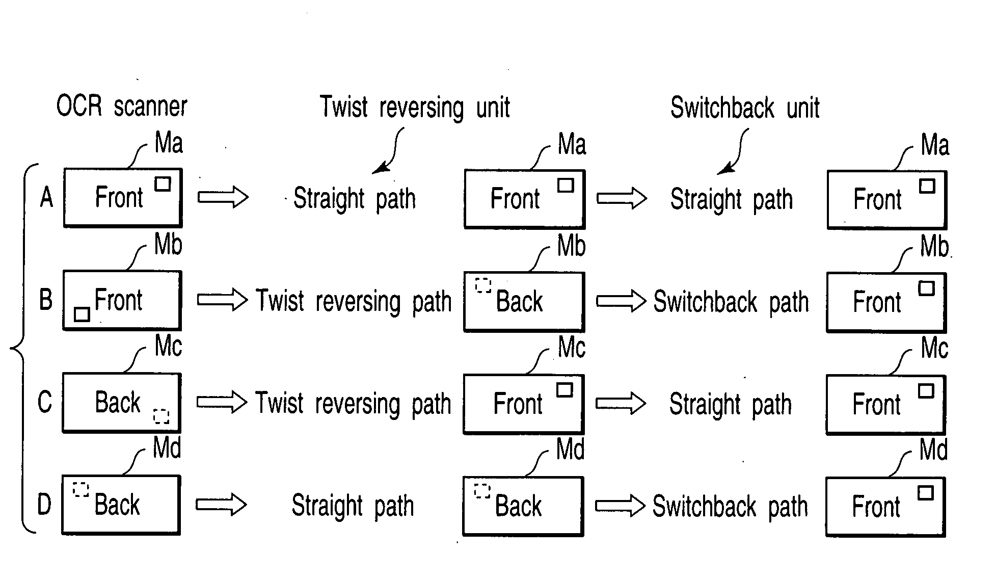
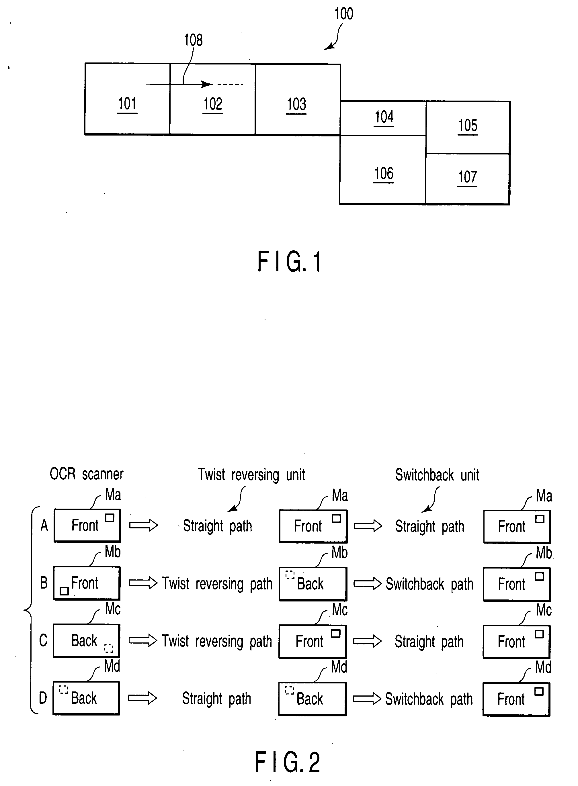
[0031]FIG. 1 diagrammatically shows a mail sorting / adjusting stamping apparatus 100 (hereinafter simply called a stamping apparatus 100) having a switchback apparatus according to an embodiment of the invention.

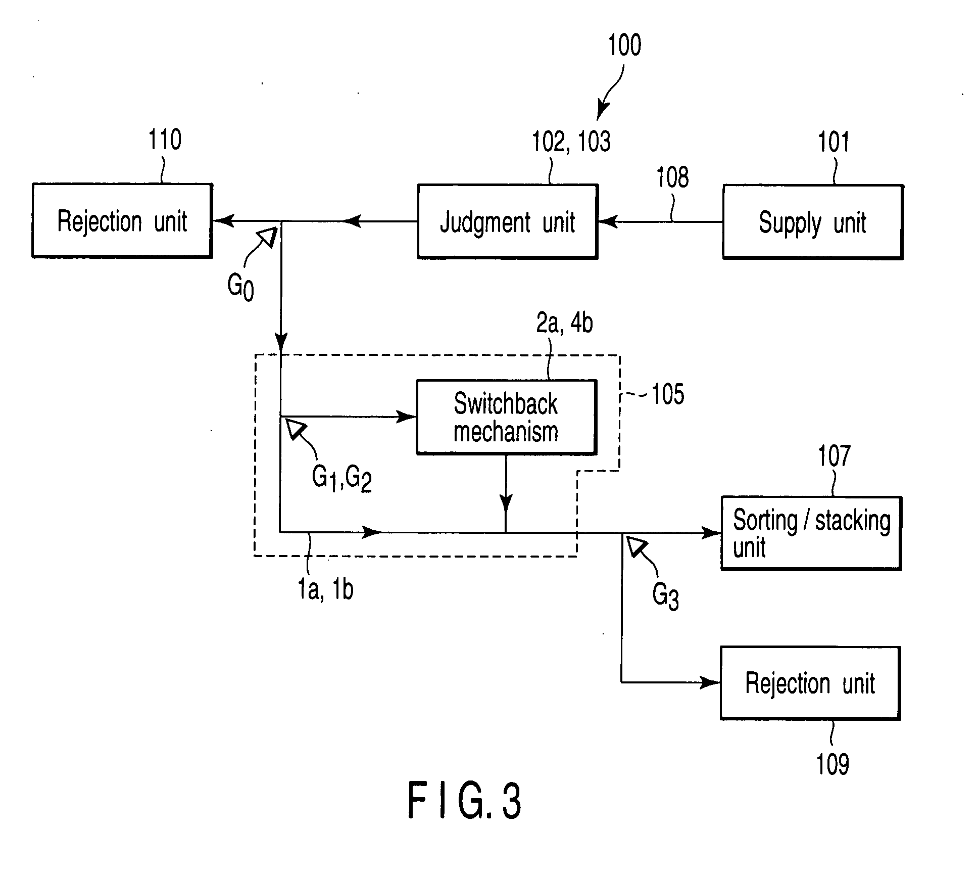
[0032]The stamping apparatus 100 has a supply unit 101, a mechanical detector 102, an OCR scanner 103, a twist reversing unit 104, a switchback apparatus 105, a stamping unit 106, and a sorting / stacking unit 107, along a mail item M (sheet) conveying direction. The stamping apparatus 100 has a conveying unit 108 to convey a mail item M throughout the component units. The stamping apparatus 100 has a not-shown operation panel to give the apparatus instructions for changing operation modes and displaying errors.

[0033]The supply unit 101 accepts a large number of regular-size mail items M with fixed thickness and width along the direction orthogonal to a conveyi...


PUM

PropertyMeasurementUnit
Timeaaaaaaaaaa

Abstract

A switchback mechanism for reversing a mail item conveying direction has a switchback roller which holds the mail item in a nip and rotates in both forward and backward directions. When there is a remaining mail item deviated from the nip of the switchback roller and remaining in the switchback unit, a pressure roller is pressed to an output roller always rotating in the direction of R1, the remaining mail item is held and fed out to the nip. At this time, a control unit takes out the remaining mail item at timing not to interfere with other mail items.

Description

CROSS-REFERENCE TO RELATED APPLICATIONS[0001]This application is based upon and claims the benefit of priority from prior Japanese Patent Application No. 2006-075106, filed Mar. 17, 2006, the entire contents of which are incorporated herein by reference.BACKGROUND OF THE INVENTION[0002]1. Field of the Invention[0003]The present invention relates to a switchback mechanism to reverse a paper sheet conveying direction, a switchback apparatus provided with at least one switchback mechanism and a bypass conveying path to bypass the switchback mechanism, and a switchback method.[0004]2. Description of the Related Art[0005]There is a conventional switchback apparatus, which accepts a paper sheet conveyed in a first direction in a nip of a switchback roller rotating in a first direction, feeds the sheet in the first direction, stops once while holding the sheet in the nip, and reverses the sheet conveying direction by rotating the switchback roller in a second direction opposite to the firs...

Claims


Application Information

Patent Timeline
20 Sep 2007
Publication
US20070216085A1
IPC
B65H29/00
CPC
B65H15/00; B65H2301/33312; B65H2404/1441; B65H2511/51; B65H2511/528; B65H2601/11; B65H2701/1916; B65H2220/01
Inventors
ASARI, YUKIO; NARUOKA, YOSHIHIKO