
Capacitive touch device and operating method thereof

Pending Publication Date: 2021-06-10
PIXART IMAGING INC
View PDF9 Cites 1 Cited by
  • Summary
  • Abstract
  • Description
  • Claims
  • Application Information

AI Technical Summary

Benefits of technology

The patent provides a capacitive touch device and method that improves touch identification accuracy by double checking touch events through a null frame during sleep mode and a driven frame during normal mode. The method also compares noise magnitudes in different frequency bands with noise thresholds to further enhance accuracy. Additionally, the sleep mode allows for scanning a smaller number of electrodes or regions, reducing power consumption.

Problems solved by technology

Said driving circuit still consumes significant electricity.

Method used


Image

  • Capacitive touch device and operating method thereof
  • Capacitive touch device and operating method thereof
  • Capacitive touch device and operating method thereof

Examples


Embodiment Construction

[0025]It should be noted that, wherever possible, the same reference numbers will be used throughout the drawings to refer to the same or like parts.

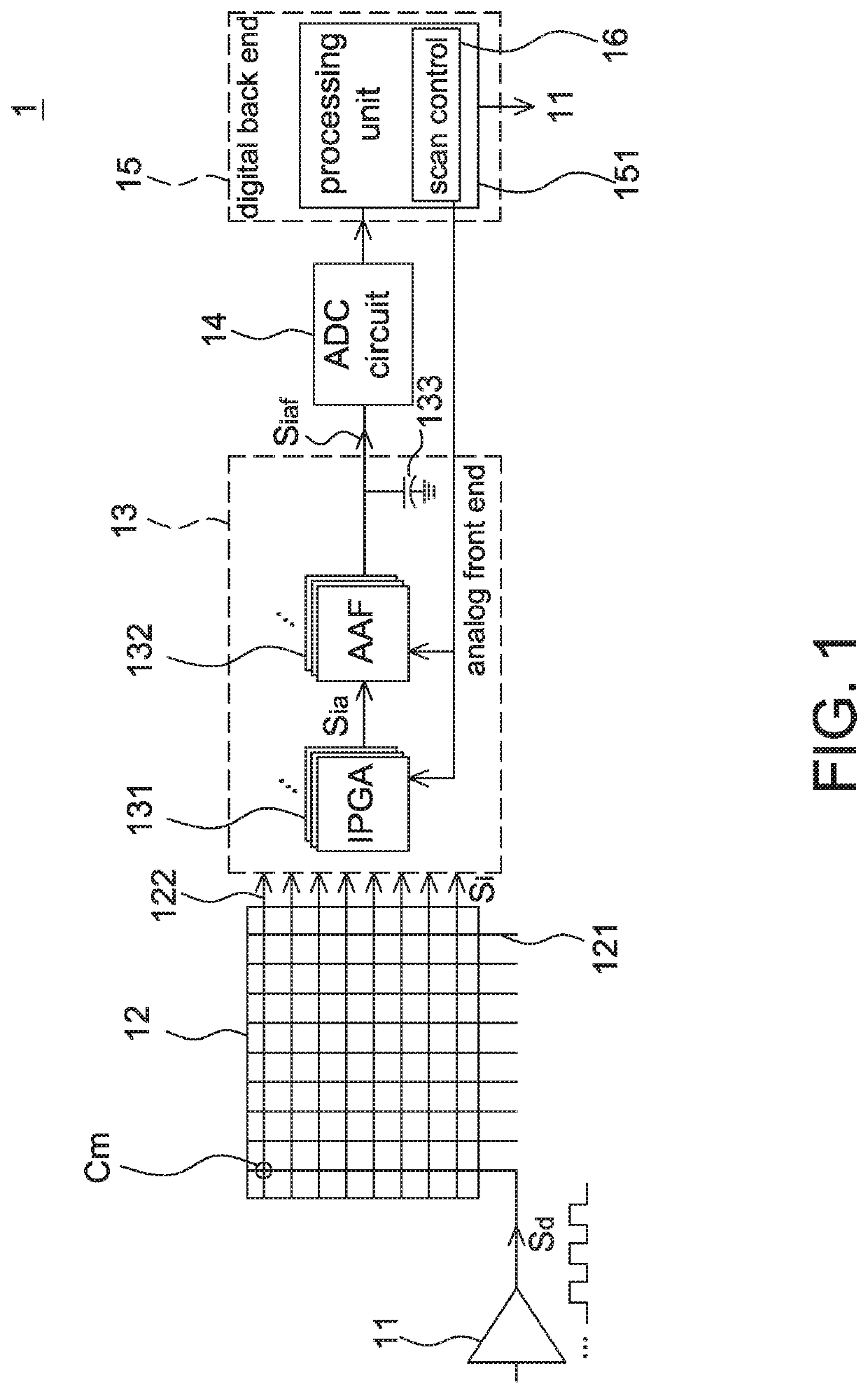
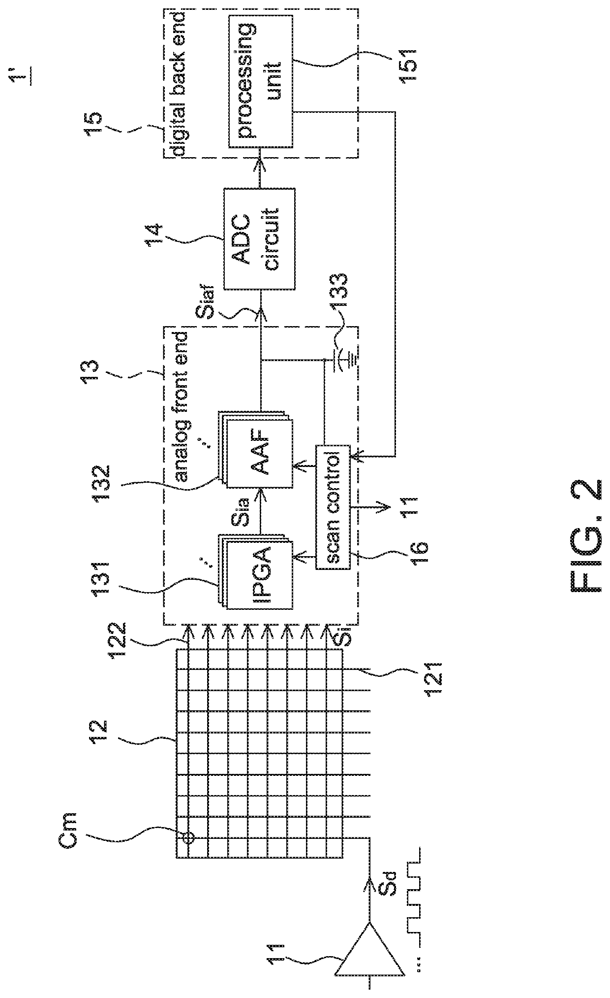
[0026]Referring to FIG. 1, it is a schematic block diagram of the capacitive touch system according to one embodiment of the present disclosure. The capacitive touch system 1 includes a plurality of driving units 11, a touch panel 12, an analog front end 13, an analog-to-digital conversion (ADC) circuit 14 and a digital back end 15. In some embodiments, the ADC circuit 14 may be included in the analog front end 13.

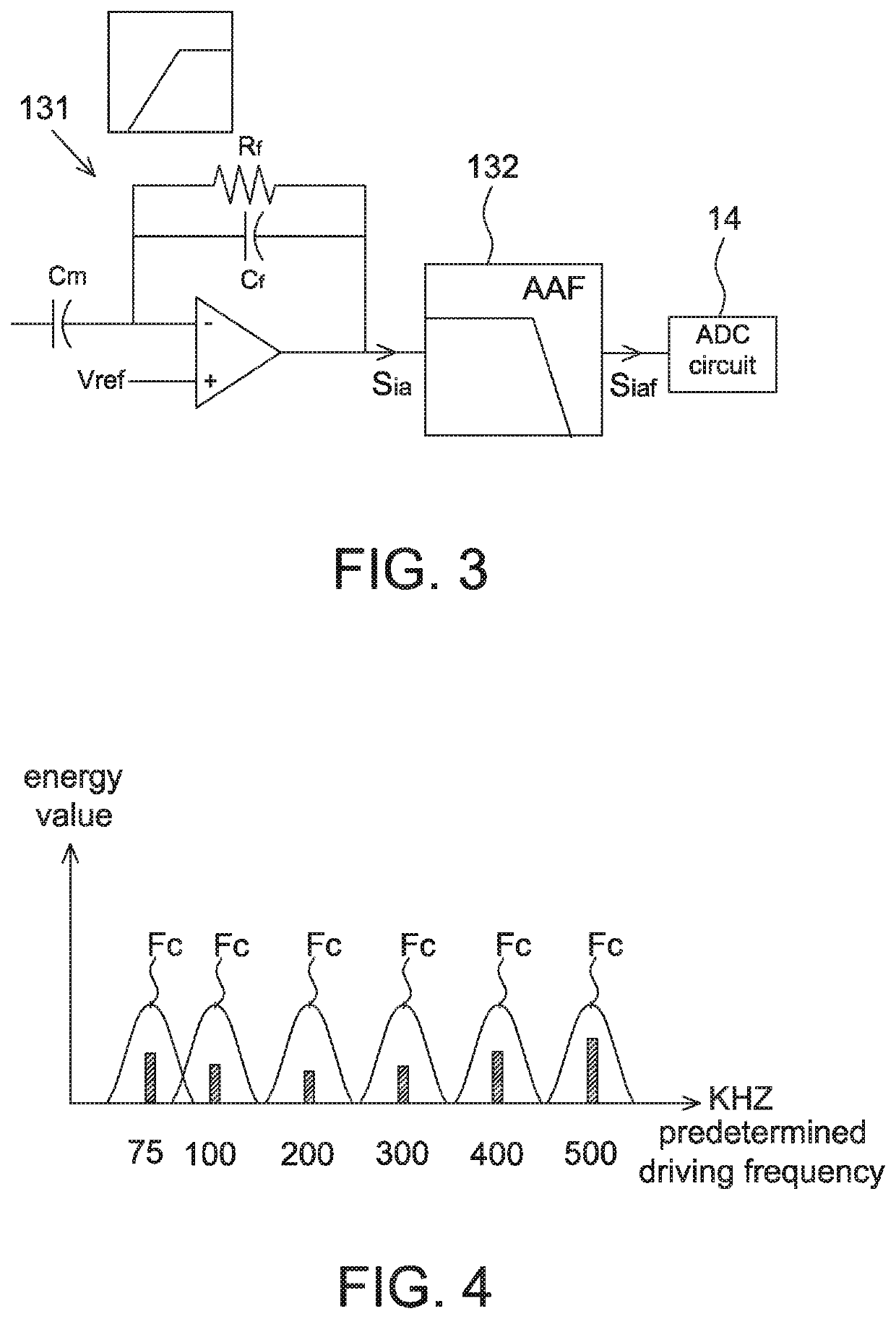
[0027]The analog front end 13 is configured to pre-process the analog signal outputted from the touch panel 12. Then, the pre-processed analog signal is converted to the digital signal by the ADC circuit 14 for the post-processing of the digital back end 15. Said pre-processing includes, for example, the amplification, downconversion, accumulation and filtering of the analog signal, but not limited thereto. Said post-processin...


PUM


Abstract

There is provided a capacitive touch device including a touch panel, a plurality of driving circuits, an analog front end and a digital back end. In a sleep mode, the plurality of driving circuits does not output driving signals to the touch panel, and the analog front end converts amplified and filtered noises outputted from the touch panel to digital signals. The digital back end identifies whether to leave the sleep mode according to the digital signals.

Description

BACKGROUND1. Field of the Disclosure[0001]This disclosure generally relates to an interactive input device and, more particularly, to a capacitive touch device and an operating method thereof capable of reducing the power consumption in the sleep mode.2. Description of the Related Art[0002]As the capacitive touch panel can provide a better user experience, it has been broadly applied to various electronic devices, e.g. applied to a display device so as to form a touch display device.[0003]Generally speaking, if a capacitive touch panel is not operated by a user for a predetermined period of time, a sleep mode is entered to save power. In the sleep mode, the capacitive touch panel continuously to perform the scanning to confirm whether the sleep mode should be left. The power saving purpose can be achieved by reducing the scan frequency, scanning a part of electrodes or changing to a self-capacitance mode in the sleep mode. However, no matter which of the above mentioned method is ad...

Claims


Application Information

Patent Timeline
IPC IPC(8): G06F3/044G06F3/041G06F3/05
CPCG06F3/0446G06F3/05G06F3/041662G06F3/04182G06F3/044G06F1/3262G06F1/3206G06F3/04166G06F3/0418
Inventor LEE, CHIA-YI
Owner PIXART IMAGING INC
Learn More