Power supply device for a vehicle

a power supply device and vehicle technology, applied in electric devices, battery/fuel cell control arrangements, cell components, etc., can solve problems such as lack of safety, and achieve the effect of downsizing the safety plug

Active Publication Date: 2007-09-20
YAMAHA MOTOR CO LTD
View PDF4 Cites 43 Cited by
  • Summary
  • Abstract
  • Description
  • Claims
  • Application Information

AI Technical Summary

Problems solved by technology

However, the structure disclosed in JP 2004-007919 lacks safety.

Method used


Image

  • Power supply device for a vehicle
  • Power supply device for a vehicle
  • Power supply device for a vehicle

Examples


Embodiment Construction

[0035] In the following detailed description, terms of orientation such as “right,”“left,”“front,”“rear,”“frontward,” and “rearward” are used herein to simplify the description of the context of the illustrated embodiments. Moreover, left, right, front and rear directions are described hereinbelow as directions as seen from a driver seated on a seat of a vehicle, such as a motorcycle. Likewise, terms of sequence, such as “first” and “second,” are used to simplify the description of the illustrated embodiments. Because other orientations and sequences are possible, however, the present invention should not be limited to the illustrated orientation. Those skilled in the art will appreciate that other orientations of the various components described above are possible.

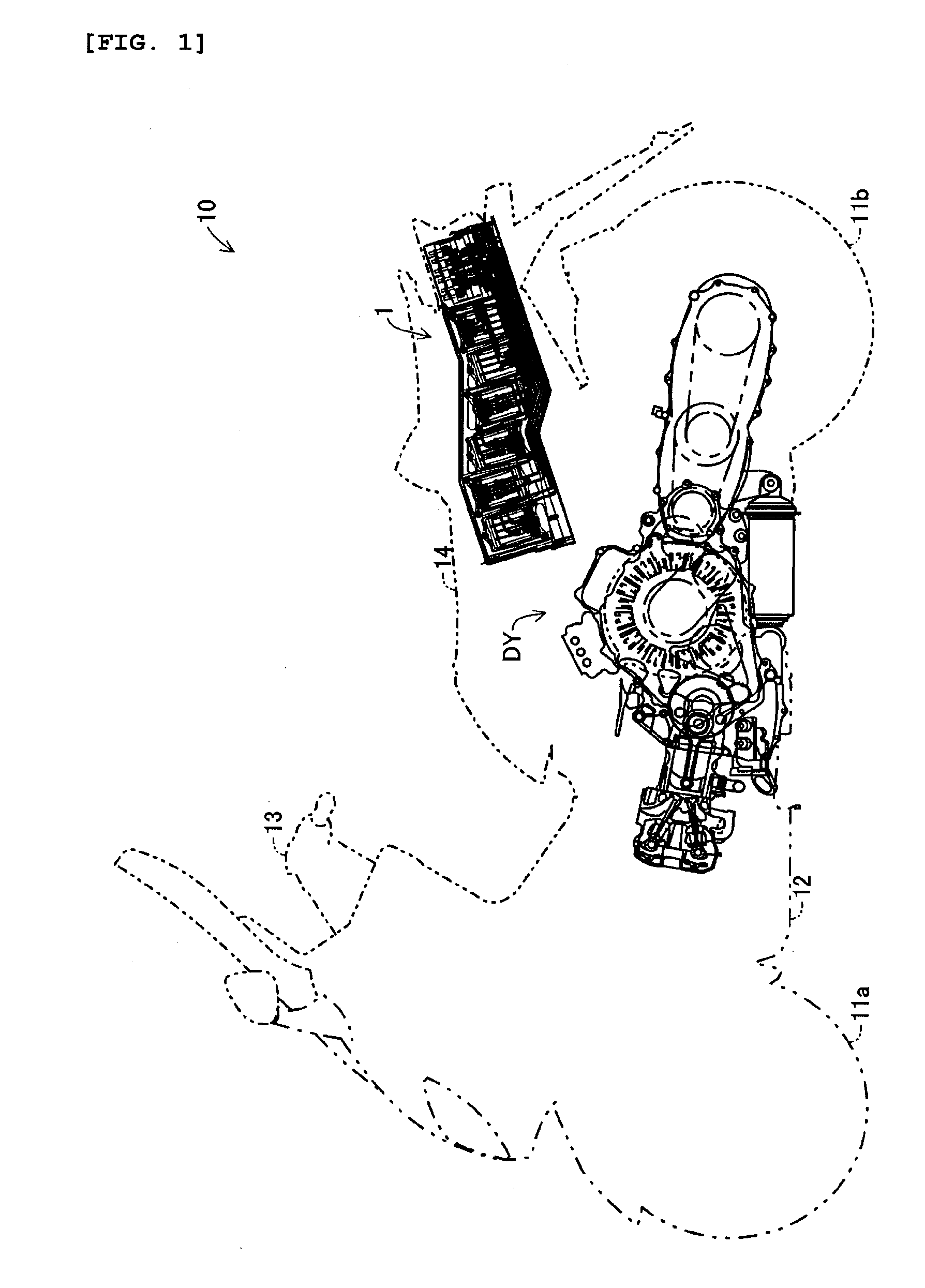
[0036]FIG. 1 shows one embodiment of a hybrid type motorcycle 10. This hybrid type motorcycle has a front wheel 11a and a rear wheel 11b. A drive unit DY can be disposed in a center lower portion of a vehicle body 12 def...


PUM


Abstract

A high voltage power supply device has a plurality of battery modules connected to each other in series by coupling a safety plug unit to a safety plug unit connecting base to output a series voltage from a power supply output coupler. The safety plug unit connects / disconnects electrode terminals of all the battery modules to each other. Female electrode bodies electrically connected to power supply terminals of the respective battery modules are collectively positioned in a limited area and are arranged at equal intervals on the safety plug unit connecting base. An output voltage of each battery module is set to be lower than 50V to reduce the risk of injury during use, inspection or maintenance of the high voltage power supply device and to downsize the device.

Description

CROSS-REFERENCE TO RELATED APPLICATIONS [0001] The present application is based on and claims priority under 35 U.S.C. § 119 to Japanese Patent Application No. 2006-075500, filed on Mar. 17, 2006, the entire contents of which are expressly incorporated by reference herein. BACKGROUND OF THE INVENTION [0002] 1. Field of the Invention [0003] This invention relates to a high voltage power supply device for a vehicle such as, for example, a hybrid vehicle or an electric vehicle which are driven at least in part by an electric motor. Although not limited thereto, the invention has applicability to two-wheeled vehicles. [0004] 2. Description of the Related Art [0005] Conventional electric automobiles run using an electric motor driven by electric power from batteries. Conventional hybrid vehicles in turn run using a combination of a gasoline engine and an electric motor. In such vehicles, a power supply battery device is required to supply high voltage for operating an electric motor so a...

Claims


Application Information

Patent Timeline
Patent Type & Authority Applications(United States)
IPC IPC(8): B60L1/00B60L50/16
CPCB60L3/04B60L3/0007B60L3/0046B60L3/0069B60L2200/12B60L2270/147B60L50/16B60L50/64B60L50/66B60L58/18Y02T10/70Y02T10/7072
Inventor MATSUMOTO, TAKAIEHOSOI, YUKIHARUSUZUKI, SHIGETOIKEDA, TAKESHIFUKUDOME, TOSHINORI
Owner YAMAHA MOTOR CO LTD
Why Eureka
Try Eureka