Method and apparatus for adjusting a chrominance signal

a chrominance signal and adjusting technology, applied in the direction of electrical equipment, color television details, television systems, etc., can solve the problems of affecting the quality of chrominance, the difference was barely visible, and the corresponding shift in chrominance was slower, so as to improve the quality of colour enhancement, avoid amplification of noise in smooth regions, and improve the effect of colour enhancement quality

Active Publication Date: 2007-09-20
VESTEL ELEKTRONIK SANAYI & TICARET ANONIM SIRKETI
View PDF8 Cites 13 Cited by
  • Summary
  • Abstract
  • Description
  • Claims
  • Application Information

AI Technical Summary

Benefits of technology

[0021] In an embodiment of the method described above, the chrominance of said current pixel is also adjusted in accordance with whether said original chrominance signal is rising or falling at said edge. By taking into account whether said original chrominance signal is rising or falling at said edge, the method is able to produce better results, especially in the presence of noise.
[0022] In an embodiment of the method described above, the chrominance of said current pixel is also adjusted in accordance with the strength of said edge. This helps to improve the quality of the colour enhancement and helps to avoid amplification of noise in smooth regions of the image.
[0023] The method is preferably repeated for plural pixels in a line of pixels. As will be discussed further below, the greatest benefits are obtained when improving colour transitions in a horizontal direction across rows of pixels in the image. Nevertheless, the method may alternatively or additionally be applied vertically to columns of pixels in the image.

Problems solved by technology

The way that this manifests itself in the displayed image is that, at an edge in an image, whereas the luminance might for example shift rapidly from a bright region to a neighbouring dark region, the corresponding shift in the chrominance is slower such that there is often a mismatch between the chrominance edges and the luminance edges.
In early colour televisions, this difference was barely visible owing to the relatively poor quality of colour reproduction at the time.
However, with more modern television sets, including particularly the large sized displays that can be achieved with LCD and plasma display panels, the visibility of hue distortions around the colour edges has become a more significant problem.
However, this method is rather basic and does not produce optimal results.
A particular problem with the method of US-A-2003 / 0107678 is its use of and reliance on the second derivative of the original chrominance signal.

Method used


Image

  • Method and apparatus for adjusting a chrominance signal
  • Method and apparatus for adjusting a chrominance signal
  • Method and apparatus for adjusting a chrominance signal

Examples


Embodiment Construction

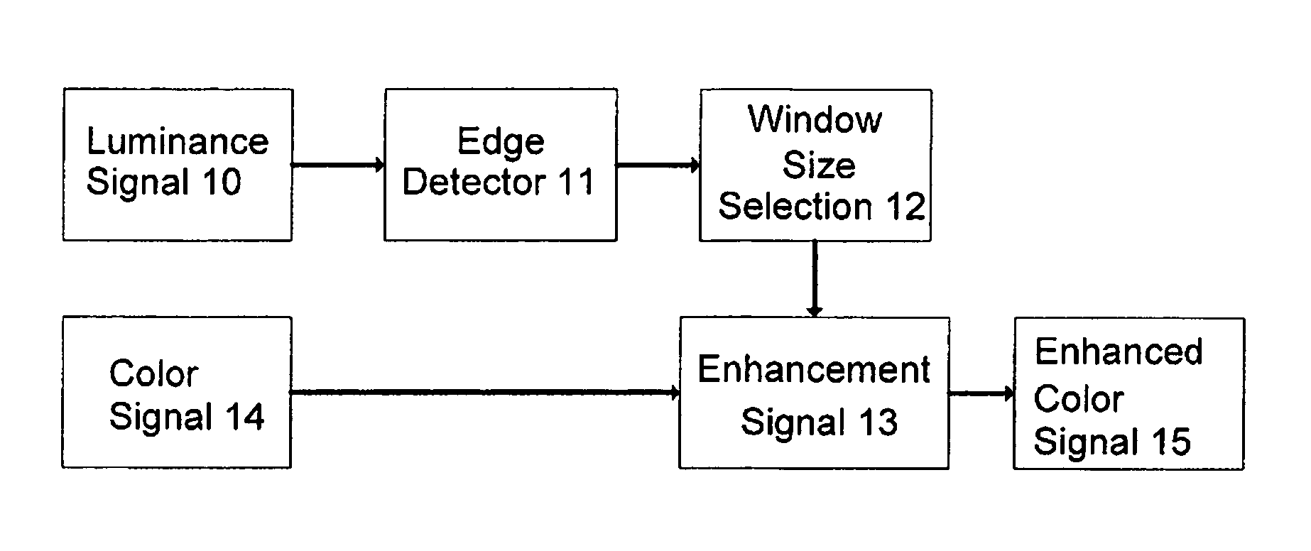
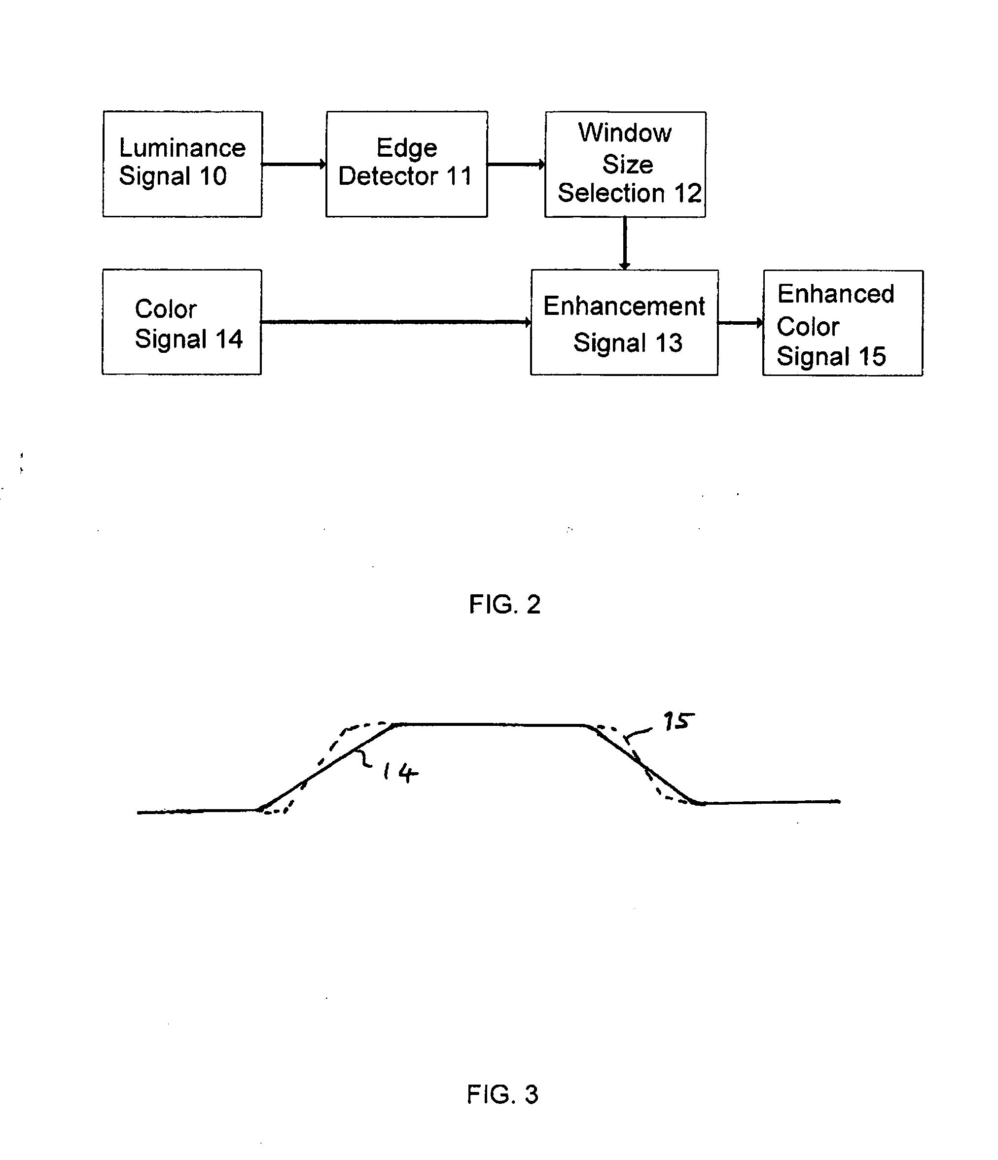
[0042] The main purpose of the preferred embodiment described herein is to align chrominance transition edges more closely with the corresponding luminance transition edges in a composite video signal so as to reduce or eliminate hue change artefacts which can otherwise arise. The most preferred embodiment adapts the weight of the transient improvement to local image features, which helps to prevent noise in smooth regions of the image being amplified.

[0043] As is known, composite colour video signals place low-pass filtered chrominance signals in the luminance signals line-by-line in a horizontal direction across rows of pixels. Thus, it is in practice only the horizontal chrominance transitions that are degraded and that are ideally improved. The vertical sampling frequency depends on the number of lines in a frame of the moving image, and no bandwidth reduction is applied to the chrominance signals in the vertical direction. Accordingly, the preferred embodiment operates prefere...


PUM


Abstract

A composite video signal has a chrominance signal (14) and a luminance signal (10). A method and apparatus are disclosed for adjusting the chrominance signal (14) to obtain an enhanced chrominance signal (15) in which at least some transitions in the enhanced chrominance signal (15) align more closely with edges in the luminance signal (10) than transitions in the original chrominance signal (14) align with edges in the luminance signal (10). An edge in the luminance signal (10) of the composite video signal is detected (11). The position of the edge relative to a current pixel is detected (11). The chrominance of the current pixel is adjusted (13) in accordance with at least the position of said current pixel relative to the edge to obtain an enhanced chrominance signal (15).

Description

CROSS-REFERENCE TO RELATED APPLICATIONS [0001] Not Applicable. STATEMENT REGARDING FEDERALLY SPONSORED RESEARCH OR DEVELOPMENT [0002] Not Applicable. FIELD OF THE INVENTION [0003] The present invention relates to a method and apparatus for adjusting a chrominance signal of a composite video signal having said chrominance signal and a luminance signal to obtain an enhanced chrominance signal. BACKGROUND OF THE INVENTION [0004] As is known, picture signals in general have a luminance or brightness signal component, which determines the brightness level of pixels at any particular time, and a chrominance or colour signal component, which determines the colour level of pixels at any particular time. In for example the television formats NTSC, PAL and SECAM, a composite colour video signal includes both luminance and chrominance signals. The way these signals are generated and used differ in detail between the different television formats, but those differences are not material for prese...

Claims


Application Information

Patent Timeline
Patent Type & Authority Applications(United States)
IPC IPC(8): H04N5/21
CPCH04N9/646
Inventor ARICI, TARIKALTUNBASAK, YUCEL
Owner VESTEL ELEKTRONIK SANAYI & TICARET ANONIM SIRKETI
Why Eureka
Try Eureka