
Core Drilling Device With Electrical Feeding That Is Manually Controlled

a technology of electrical feeding and drilling device, which is applied in the direction of portable drilling machine, manufacturing tools, working accessories, etc., can solve the problems that the initial phase of drilling operation has not been able to be automated in a satisfactory way

Inactive Publication Date: 2007-09-20
HUSQVARNA AB
View PDF2 Cites 38 Cited by
  • Summary
  • Abstract
  • Description
  • Claims
  • Application Information

AI Technical Summary

Benefits of technology

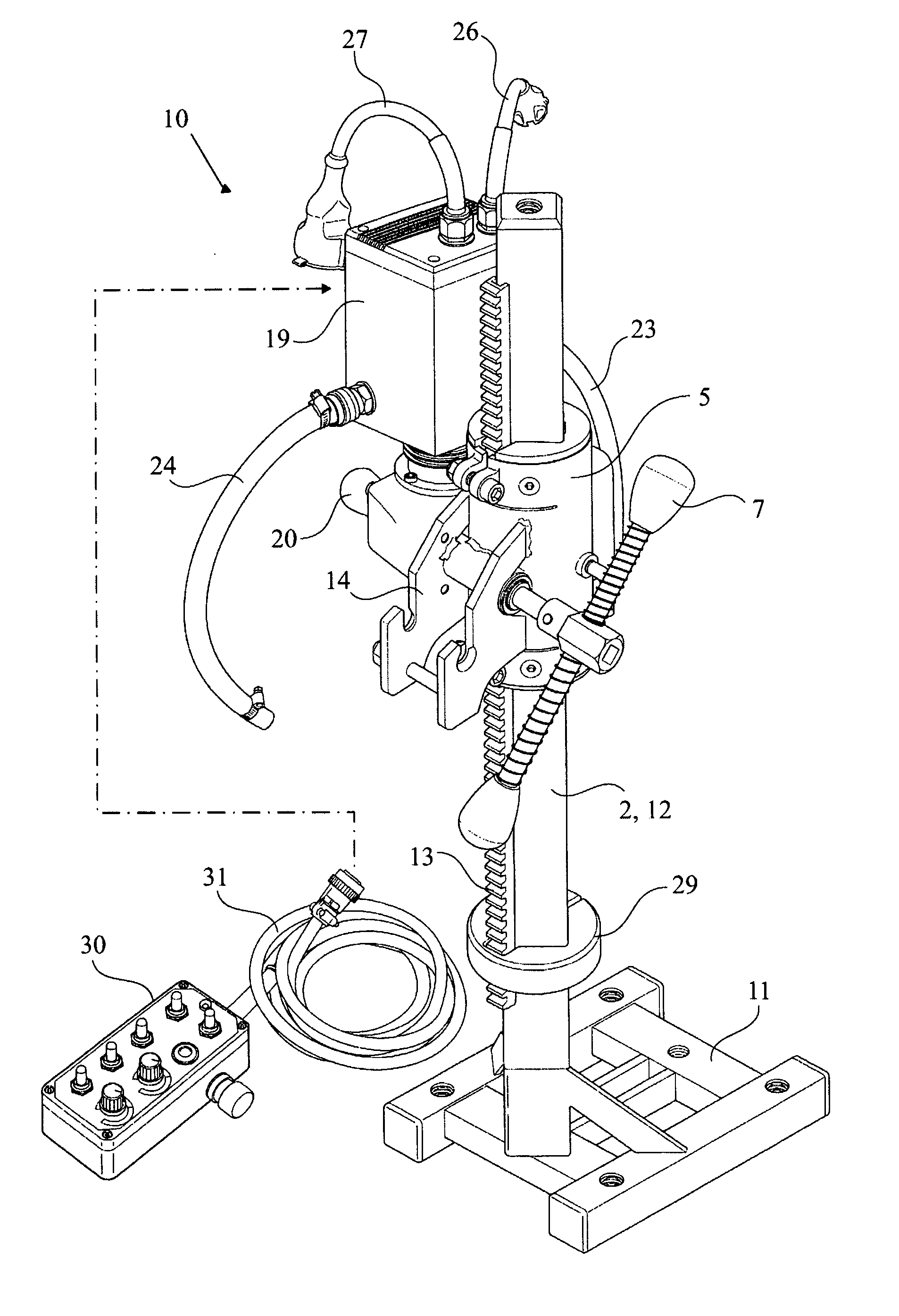
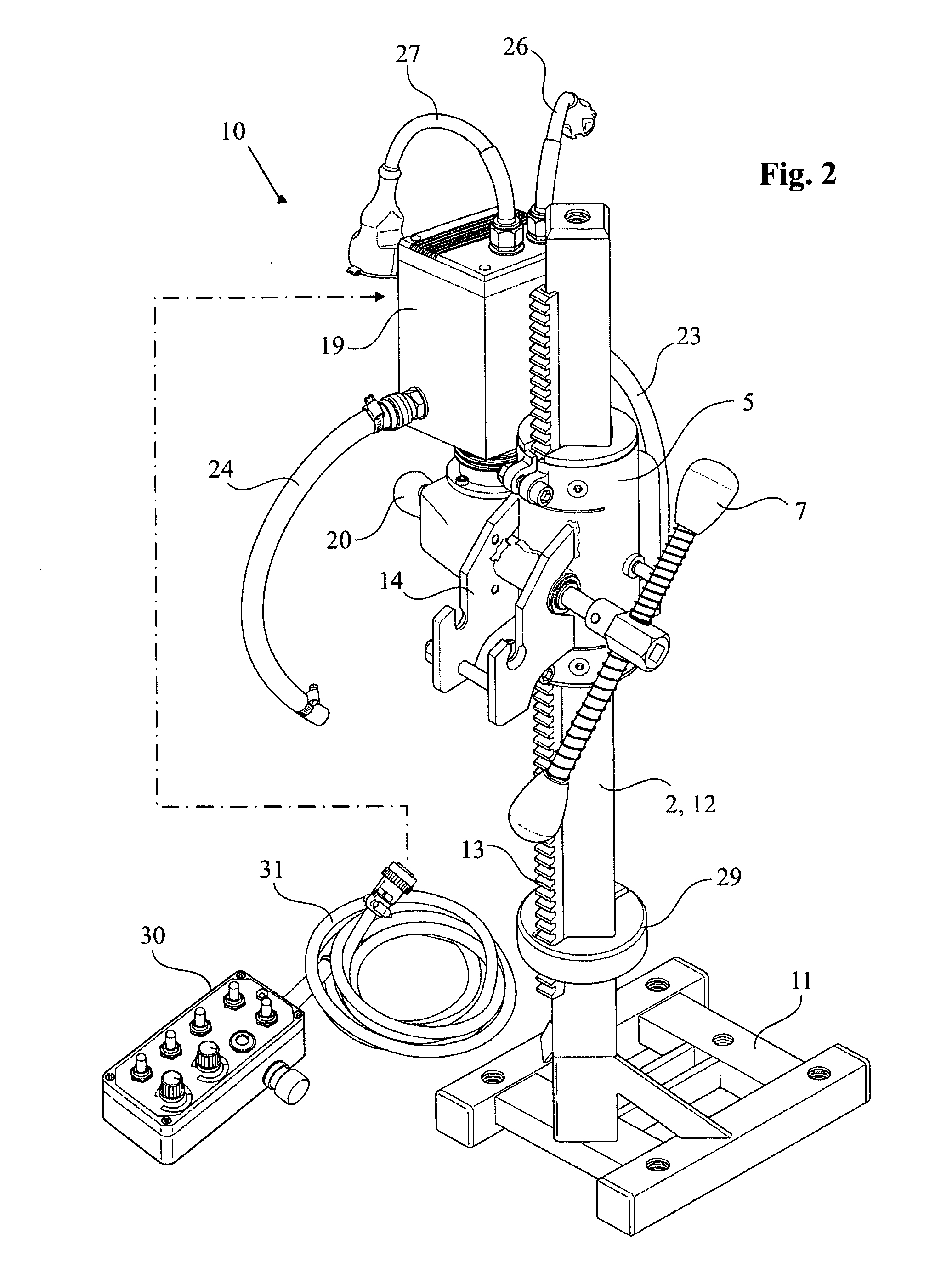
[0003] The purpose of the invention is to resolve the above-mentioned problem. According to a first aspect of the invention, this is achieved by means of a control unit that is electrically connected to the feeding unit, this feeding unit comprising at least a first control for manual influence of the feeding force of the feeding motor. According to a preferred embodiment, the control unit constitutes a portable unit, for instance in the form of a relatively small box that via at least one cable and / or via radio communication is electrically connected to the feeding unit. This makes it possible, even during the initial critical drilling phase, to remote control the core-drilling device, which can imply both ergonomic and safety related advantages. This does not however mean that the control unit cannot be located on the feeding unit or at any other location on the device, but rather means a freedom from such a mounting.

Problems solved by technology

A problem with this known device is however that the initial phase of the drilling operation has not been possible to automate in a satisfactory way.
Apart from the fact that the initial, manual operation is difficult to carry out and requires skill and experience, it has also in many cases ergonomic disadvantages, especially when the drilling holes are to be established in inaccessible locations, such as in ceilings, close to corners and so on, which may require ladders etc.

Method used


Image

  • Core Drilling Device With Electrical Feeding That Is Manually Controlled
  • Core Drilling Device With Electrical Feeding That Is Manually Controlled
  • Core Drilling Device With Electrical Feeding That Is Manually Controlled

Examples


Embodiment Construction

[0003] The purpose of the invention is to resolve the above-mentioned problem. According to a first aspect of the invention, this is achieved by means of a control unit that is electrically connected to the feeding unit, this feeding unit comprising at least a first control for manual influence of the feeding force of the feeding motor. According to a preferred embodiment, the control unit constitutes a portable unit, for instance in the form of a relatively small box that via at least one cable and / or via radio communication is electrically connected to the feeding unit. This makes it possible, even during the initial critical drilling phase, to remote control the core-drilling device, which can imply both ergonomic and safety related advantages. This does not however mean that the control unit cannot be located on the feeding unit or at any other location on the device, but rather means a freedom from such a mounting.

[0004] Further characterisation and aspects of the invention ar...


PUM

PropertyMeasurementUnit
idling currentaaaaaaaaaa
timeaaaaaaaaaa

Abstract

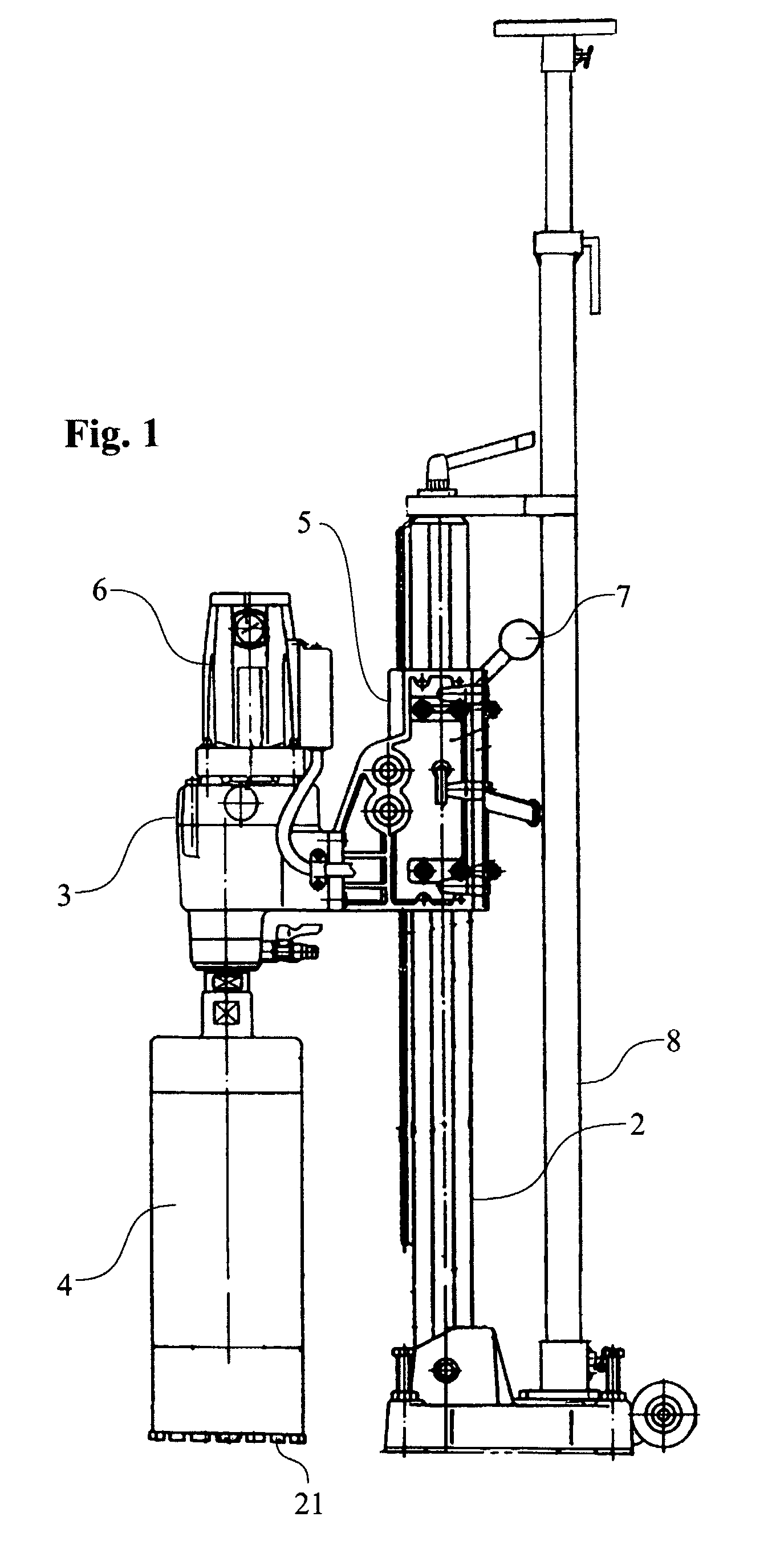
A core-drilling device (10) comprising a drilling machine (3) with a core drill (4), a drill stand (2), a feeding housing suspending the drilling machine and which is movable along the stand, an electric drilling motor for rotation of the core drill in the drilling machine and a feeding unit (19) with an electric feeding motor (17) for the feeding of the feeding housing along the stand. A control unit (30), which is electrically connected to the feeding unit, comprises at least a first control (33) for manual influence of the feeding motor's (17) feeding force.

Description

TECHNICAL FIELD [0001] The present invention relates to a core-drilling device comprising a drilling machine with a core drill, a drill stand, a feeding housing that supports the drilling machine and that is movable along the stand, an electric drilling motor for the rotation of the core drill in the drilling machine and a feeding unit with an electric feeding motor for the feeding of the feeding housing along the stand. A control unit is electrically connected to the feeding unit, the mentioned control unit comprising at least a first control for manual influence of the feeding motor's feeding force. TECHNICAL BACKGROUND [0002] Automatically operating core-drilling devices of the above-mentioned type are known. A problem with this known device is however that the initial phase of the drilling operation has not been possible to automate in a satisfactory way. The reason is that the tube-shaped core drill, which can have a very large diameter, easily slides sideways when a section of...

Claims


Application Information

Patent Timeline
Patent Type & Authority Applications(United States)
IPC IPC(8): B23B47/06B23BB23B45/02B28D1/04B28D1/14B28D7/00
CPCB25H1/0064Y10T408/675B28D7/005B28D1/041
Inventor LARSSON, MARTIN
Owner HUSQVARNA AB
Learn More