Loading Apparatus

a technology of loading apparatus and bucket, which is applied in the direction of lifting devices, thin material handling, construction, etc., to achieve the effect of ensuring the large rotatable range of the bucket, simplifying the loading apparatus, and enhancing the freedom degree of design of the bucket link

Inactive Publication Date: 2007-09-20
YANMAR CO LTD +1
View PDF0 Cites 21 Cited by
  • Summary
  • Abstract
  • Description
  • Claims
  • Application Information

AI Technical Summary

Benefits of technology

[0013] According to the invention, a loading apparatus comprises: a bracket fixed on a vehicle; a lift arm pivoted at one end thereof onto the bracket; a lift arm cylinder interposed between the bracket and the lift arm and adapted to be telescoped for vertically swinging the lift arm relative to the bracket; an attachment vertically swingably pivoted onto a tip portion of the lift arm; an intermediate link pivoting an intermediate portion of the lift arm; a bucket cylinder interposed between the intermediate link and the attachment and adapted to be telescoped for vertically swinging the attachment relative to the lift arm; and a bucket link interposed between the intermediate link and the attachment so as to transmit the telescopic movement of the bucket cylinder to the attachment. The bucket link is disposed above the lift arm. The intermediate link includes a pair of left and right plates, so that a rear end portion of the bucket link is pivoted to an upper front portion of the intermediate link between the plates, a tip portion of a piston rod of the bucket cylinder is pivoted to an upper rear portion of the intermediate link between the plates, and a fore-and-aft middle portion of the lift arm is pivoted to a bottom portion of the intermediate link between the plates. The bucket link is offset laterally outward from the lift arm side. The lift arm and the bucket link are made of plates.
[0014] Therefore, the loading apparatus is simplified, expands an operator's ken for viewing a bucket or another member attached to the attachment, and ensures strengths of its components.
[0015] Further, since the lift arm is disposed at a lateral middle position between the plates of the intermediate link, and the bucket link is offset laterally outward from the lift arm between the plates of the intermediate plates so as not to vertically overlap the lift arm, the bucket link is prevented from interfering with the link arm during lifting and swinging of the bucket. Therefore, when the bucket link is operated for swinging the bucket, it is unnecessary to consider the prevention of interference of the bucket link with the lift arm, so that the freedom degree of designing the bucket link is enhanced and a large rotatable range of the bucket is ensured. The bucket link can be formed into a nearly rectilinear shape, such as to have sufficient rigidity and durability in comparison with a curved bucket link. As a result, the linkage for swinging the attachment is simplified with pivot points reduced in number, while ensuring a sufficient strength.
[0016] Further, since the lift arm and the bucket link are made of plates, the lateral width of the linkage of the loading apparatus is reduced so as to expand the sight for viewing the bucket attached to the attachment in the case where the linkage overlaps in side view by vertically moving the lift arm. Further, the loading apparatus is lightened at a side thereof toward the bucket, so as to reduce the moment applied onto the loading apparatus when the bucket is lifted up and down.
[0017] Further, a pair of left and right brackets are fixed on the vehicle. A pair of left and right bucket cylinders, a pair of left and right lift arms, and a pair of left and right lift arm cylinders are provided to the vehicle. Each of the bucket cylinders, each of the lift arms and each of the lift arm cylinders are pivoted at respective rear ends thereof to each of the brackets. In each of the brackets, a pivot center of the lift arm is disposed forward and downward from a pivot center of the bucket cylinder. In each of the brackets, a pivot center of the lift arm cylinder is disposed forward and downward from the pivot center of the lift arm.
[0018] Therefore, the linkages having the above-mentioned construction are disposed on left and right sides of the working vehicle.

Problems solved by technology

Problems to be solved are the interference of the lift arms with wheels and the expansion of the intermediate link caused when the working vehicle with the loader is minimized in the whole length.

Method used


Image

  • Loading Apparatus
  • Loading Apparatus
  • Loading Apparatus

Examples


embodiment 1

[0046] An embodiment of the invention will be described with reference to the drawings.

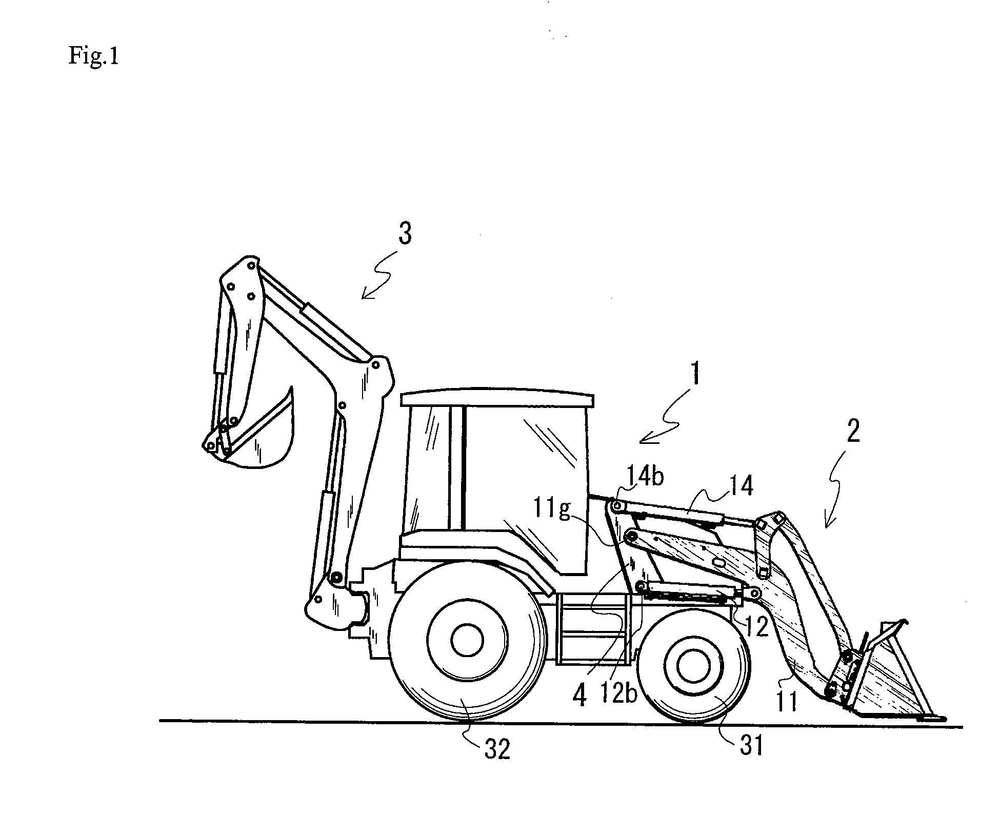
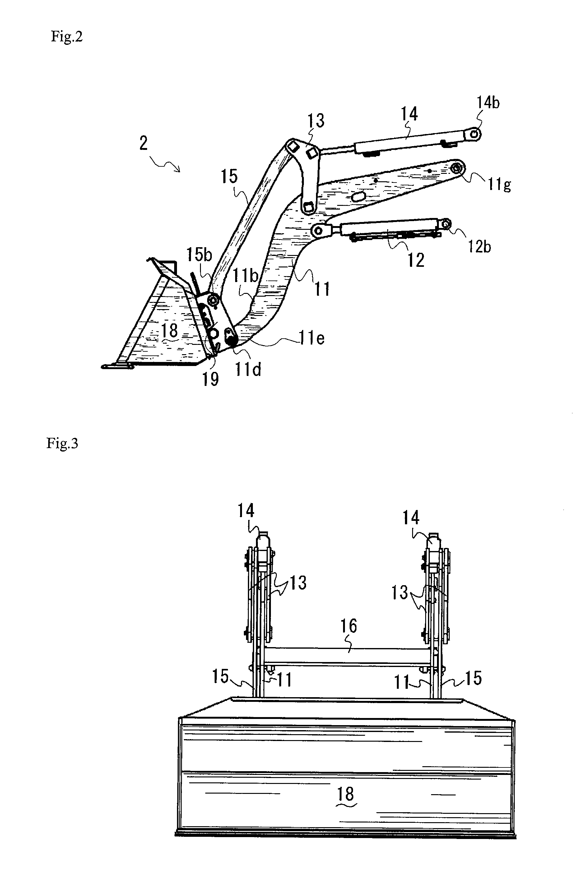
[0047]FIG. 1 is a side view of a loader attached to a working vehicle.

[0048] A working vehicle 1 is a backhoe loader, provided with front wheels 31 and rear wheels 32. Working vehicle 1 is equipped with a loader 2, serving as a loading apparatus, and an excavator 3. A pair of brackets 4 are disposed on respective left and right sides of a bonnet of working vehicle 1, and fixed to a body frame of working vehicle 1.

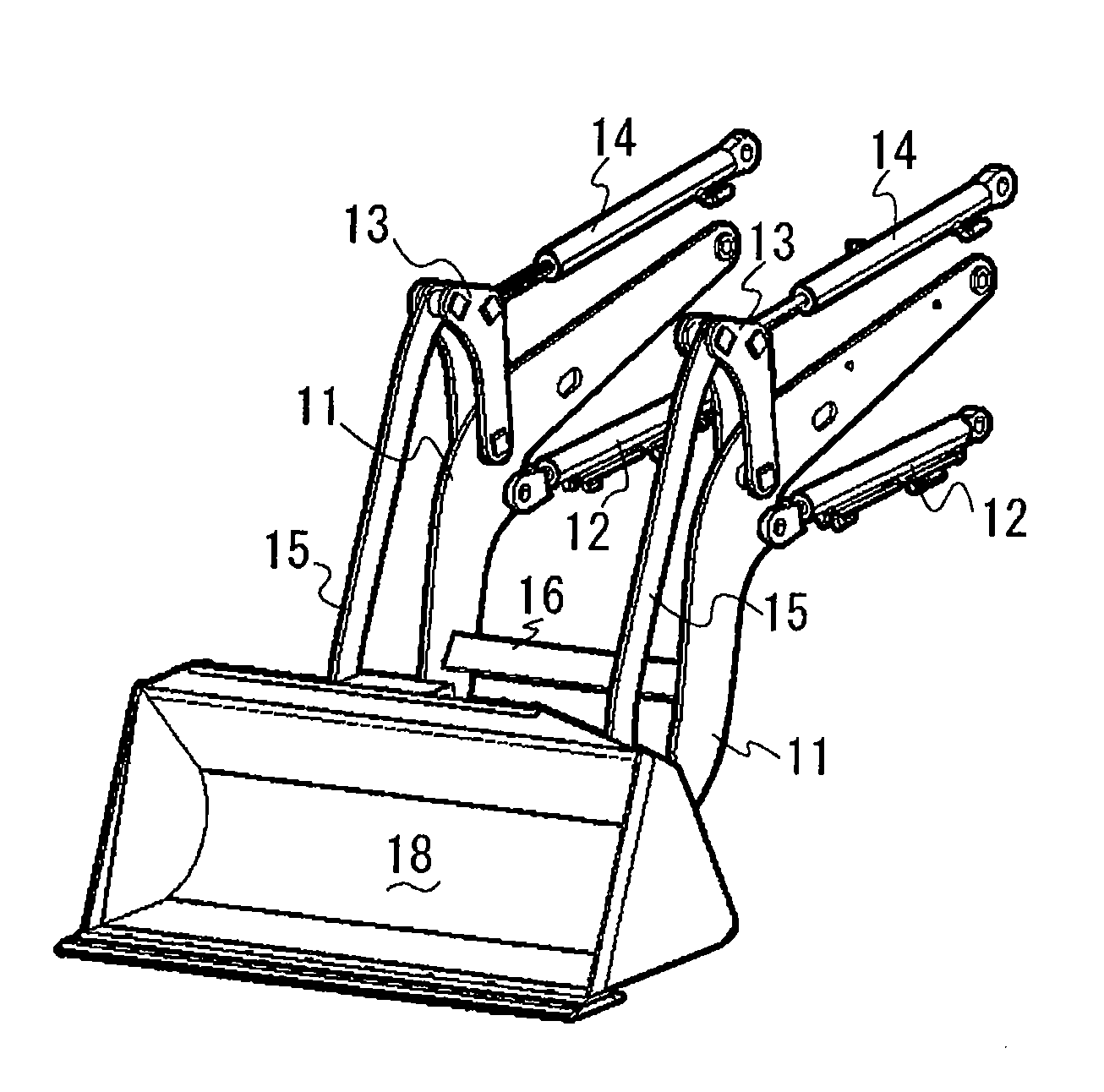
[0049] Loader 2 is attached to brackets 4 at a front portion of working vehicle 1 so as to serve as a front loader. On each bracket 4 are disposed a pivot center 11g for a lift arm 11, a pivot center 14b for a bucket cylinder 14 and a pivot center 12b for a lift arm cylinder 12. Pivot center 11g for lift arm 11 is disposed forward and downward from center pivot 14b for bucket cylinder 14. Pivot center 12b for lift arm cylinder 12 is disposed forward and downward from center pivot 11g f...

embodiment 2

[0082] A second embodiment of the invention will be described with reference to FIGS. 12 and 13.

[0083]FIG. 12 illustrates a bucket link according to a second embodiment. FIG. 12(a) is a side view of a loader according to the second embodiment, and FIG. 12(b) is a side view partly in section of the bucket link. FIG. 13 is a front view partly in section of the bucket link according to the second embodiment.

[0084] Each of bucket links 25 has a not-pivoted portion sectionally formed in a reversed U-shape when viewed in front. Referring to FIG. 13, in the reversed U-shaped section, a pair of plates 25c are extended downward from a bottom surface of a horizontal plate 25b. Each of lift arms 11 is disposed between the downwardly extended plates. Such a bucket link 25 is improved in strength while it is prevented from interfering with lift arm 11. Further, the sectional area of bucket link 25 for ensuring the rigidity is increased while bucket link 25 is vertically minimized. Therefore, t...


PUM


Abstract

A simple and compact loader having a sufficient strength with brackets fixed on a working vehicle. Lift arms are pivoted at one ends thereof to respective brackets so as to be vertically swung by respective lift arm cylinders. Attachments are vertically swingably supported on respective tip portions of the lift arms. Bucket links are connected to the respective attachments so as to transmit the telescopic action of bucket cylinders. Each of the bucket links is offset laterally from each of the lift arms. The middle portion of each of the lift arms is disposed above a straight line connecting both ends of the lift arm to each other, so as to ensure a space for arranging a steerable wheel under the lift arm.

Description

BACKGROUND OF THE INVENTION [0001] 1. Field of the Invention [0002] The invention relates to a loading apparatus (loader) attached to a working vehicle so as to be used for loading sand, bulk and so on. [0003] 2. Background Art [0004] Generally, a front loader, serving as a loading apparatus attached to a working vehicle, includes a pair of left and right lift arms, a bucket connected to tips of the lift arms, a cylinder for lifting the lift arms, and a cylinder for rotating the bucket. [0005] A normal front loader disclosed in Japanese Laid Open Gazette No. Hei 8-27842 is attached onto brackets secured on left and right sides of a rear portion of a bonnet of a tractor, serving as a working vehicle. The tractor is provided with a cylinder for rotating the lift arms below the lift arms of the front loader, and is provided with a bucket link below the lift arms. An intermediate link is attached onto an upper portion of each of the lift arms. The bucket link extended from the bracket i...

Claims


Application Information

Patent Timeline
Patent Type & Authority Applications(United States)
IPC IPC(8): B66F9/06E02F3/34
CPCE02F3/3408E02F3/34Y10S414/13
Inventor SAKADA, SEIJI
Owner YANMAR CO LTD
Why Eureka
Try Eureka