Endodontic instrument with non-conductive coating and method for locating the apex of a tooth

Inactive Publication Date: 2007-09-20
SYRIBEYS PHILIP JOHN
14 Cites 6 Cited by

AI-Extracted Technical Summary

Problems solved by technology

Many devices and techniques address measurement of root canal length, however, these devices and techniques are limited by their functionality and accuracy.
While electronic apex locaters are helpful in determining canal length, they have limitations.
Furthermore, not infrequently, a patient will have multiple sources of conductive interference which together further diminish the...

Method used

[0019]Accordingly, endodontic files, partially laminated with a non-conductive electrically insulating coating, allow the dentist to enlarge and shape the canal while at the same time monitoring canal depth—without the need to switch instruments as required through prior art approaches. In this way, the present invention not only ensures a more efficient and refined approach to securing proper canal depth, by minimizing over/under filling and over/under instrumentation, it saves the dentist and patient considerable time during endodontic procedures.
[0020]Regarding coating composition, the instruments may be coated with a variety of non-conductive electrical insulators. As non-limiting examples, the coating may be comprised of silica, silicone, alumina, diamond, diamond-like films, insulating ceramics, carbon and carbon-based films, Polytetrafluoroethylene (PTFE), or other electrically non-conductive material laminating non-conductive portion 20. In one preferred embodiment, the non-conductive coating is comprised of silica or silicon dioxide. Silica based coating...

Benefits of technology

[0009]The present invention utilizes an electrically non-conductive coating applied to dental instruments to minimize the problem of electrical interference. A further object of the invention is to provide a variety of instrument coatings with differing surface textures and abrasiveness, said coatings meeting the varied clinical needs of the dentist. Another object of the present invention is to provide an array of coated instruments with varied dimensions, including variation at the most di...

Abstract

An electrically conductive endodontic instrument coated with a non-conductive layer on a portion of the instrument wherein a proximal and distal portion of the instrument remain uncoated and capable of conducting current therethrough using a traditional apex locator or other alerting means. The non-conductive coatings avoid electrical interference from prior restorative work and anatomical variants. The coatings may be smooth to minimize resistance in the endodontic working space or relatively abrasive to facilitate filing where desired. A method for locating the apex of a tooth utilizing an endodontic instrument coated with an electrically non-conductive layer wherein a proximal and distal portion of the instrument remain uncoated and wherein the instrument is advanced in a root canal space toward the apex of a tooth. When the distal portion of the file makes contact with the apex, and a conductive portion of the file is placed in electrical contact with an apex locator, or other alerting means, said contact actuates an alert thereby establishing canal depth while the coated portion of the instrument avoids electrical artifact from prior restorative work and variant anatomy.

Application Domain

Technology Topic

Image

  • Endodontic instrument with non-conductive coating and method for locating the apex of a tooth
  • Endodontic instrument with non-conductive coating and method for locating the apex of a tooth
  • Endodontic instrument with non-conductive coating and method for locating the apex of a tooth

Examples

  • Experimental program(1)

Example

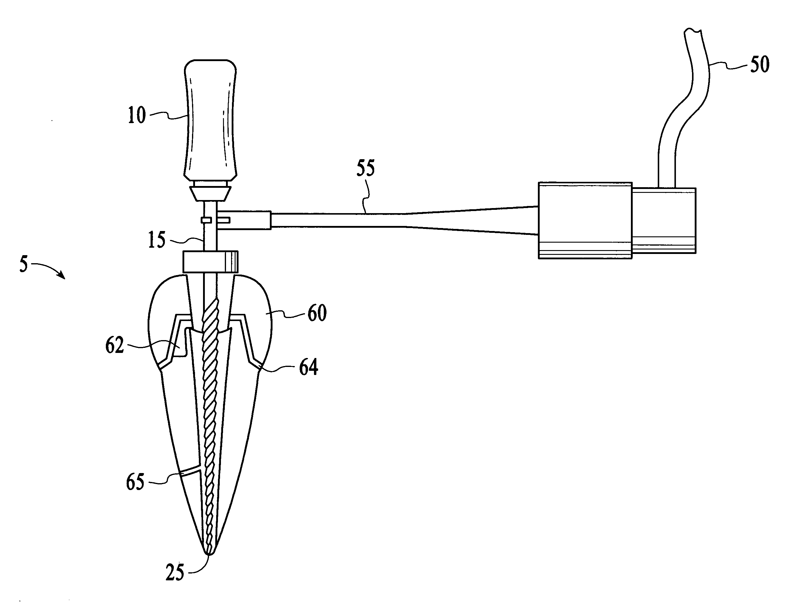
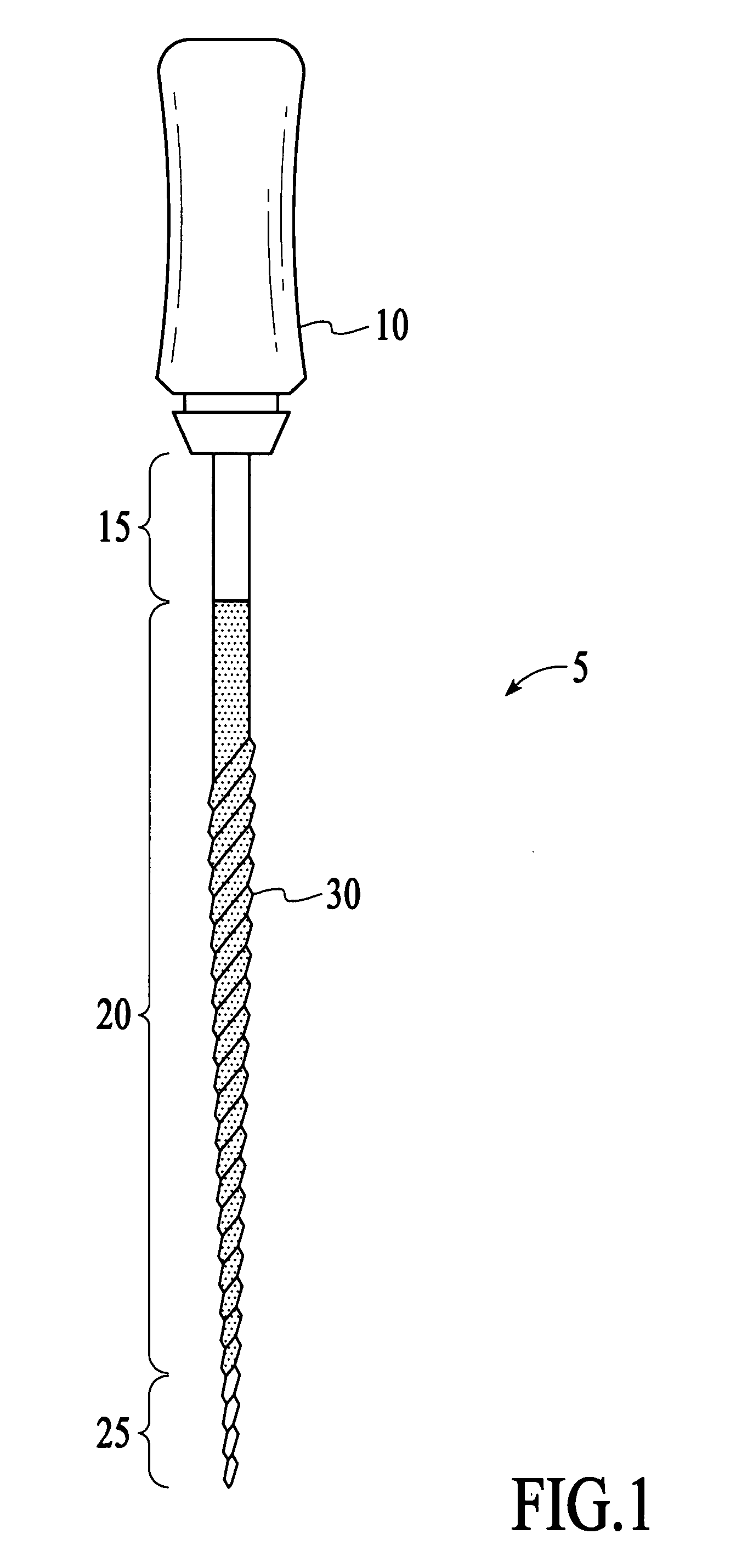
[0015]Referring now descriptively to the drawings, the attached figures illustrate example embodiments of the present invention. FIG. 1 depicts an example dental instrument with an electrically insulating, non-conductive coating. To illustrate the present invention, a non-limiting example dental file will be used herein as an exemplar instrument. The example file referred to generally as 5 has a handle 10, an electrically conductive shaft having a proximal conductive portion 15, coated non-conductive portion 20, a distal conductive portion 25, and, in this exemplar instrument, a filing portion 30 is also depicted. Non-conductive portion 20 is formed where non-conductive media is placed, preferably, uniformly and circumferentially along the conductive shaft thereby laminating the surface and rendering it non-conductive. The proximal conductive portion 15 and distal conductive portion 25 are not coated with non-conductive media. In a preferred embodiment, the proximal conductive portion 15 measures about 3 millimeters in length, although this merely represents the standard file clamp typically used in the industry, and is arbitrary with respect to the scope of the present invention.
[0016]The dimensions of distal conductive portion 25 relate directly to the size of the canal space to be examined. Root canals with larger diameters, such as those found in palatal roots and maxillary central incisor root canal spaces, utilize an endodontic file where distal conductive portion 25 measures from about 0.5 millimeter to about 1 millimeter in length. Root canals with smaller diameters, such as those found in mandibular central incisors and the mesial roots of molars, require distal conductive portion 25 to measure about 2 or 3 millimeters, depending on canal space diameter. Thus the dimensions of distal conductive portion 25 directly relate to the size of the canal space to be examined.
[0017]In a preferred embodiment, the thickness of the non-conductive coating 20 itself need not exceed 200 nanometers to inhibit the electrical conductivity properties of the instrument. However, it should be noted that the non-conductive coating 20 might be quite thick. Film thickness is limited only by the clinical utility of such an instrument with a larger cross-sectional diameter attributable to the layer. Given the inherent variations of root canal size, utilizable film thickness is guided by an individual clinical application. An instrument coated with a relatively thick layer of insulating media may have difficulty navigating the smallest portions of one canal while the identical instrument may be quite appropriate and serve well for another. One advantage to a thicker coating is that it may be more durable and resistant to corrosive effects during the cleaning. Accordingly, the invention may be practiced with a wide range of coating thicknesses.
[0018]Regarding the instruments, typically standard dental instruments are comprised of stainless steel or nickel titanium. A wide variety of instruments types may be coated, the simplest instrument being a metal wire which, at its most basic, is capable of locating the apex of a tooth. As a non-limiting example, a preferred embodiment of the present invention places a non-conductive coating on traditional dental files, including but not limited to reamers, K-Files, and Hedstrom files.
[0019]Accordingly, endodontic files, partially laminated with a non-conductive electrically insulating coating, allow the dentist to enlarge and shape the canal while at the same time monitoring canal depth—without the need to switch instruments as required through prior art approaches. In this way, the present invention not only ensures a more efficient and refined approach to securing proper canal depth, by minimizing over/under filling and over/under instrumentation, it saves the dentist and patient considerable time during endodontic procedures.
[0020]Regarding coating composition, the instruments may be coated with a variety of non-conductive electrical insulators. As non-limiting examples, the coating may be comprised of silica, silicone, alumina, diamond, diamond-like films, insulating ceramics, carbon and carbon-based films, Polytetrafluoroethylene (PTFE), or other electrically non-conductive material laminating non-conductive portion 20. In one preferred embodiment, the non-conductive coating is comprised of silica or silicon dioxide. Silica based coatings applied to instruments decrease friction and provide a relatively slippery instrument that readily slides in and out of the canal; this aids in the negotiation of relatively small, tight canal spaces. In contrast, abrasive films have unique properties and clinical utility. For example, the application of Alumina and/or Aluminum Oxide films yields an instrument coated with an abrasive layer. Similarly, diamond, diamond-like layers, and carbon-based films may provide an abrasive coating that assists in widening the canal where clinically appropriate and desired. The abrasive coatings are most advantageous where the user seeks to enlarge the canal while frequently monitoring canal depth. In this way, the integration of coating-augmented filing and depth-monitoring is particularly useful in further reducing the time of endodontic procedures. Application of the abovementioned coatings, for example, through various thin-film deposition techniques, is well recognized in the prior art. Any number of techniques may be used to deposit the coating layer on the instrument.
[0021]Regarding the apex locating system, FIGS. 2 and 3 illustrate an electrically conductive dental instrument 5 comprising a proximal conductive portion 15, middle non-conductive portion 20, and distal conductive portion 25, wherein said middle portion 20 is coated with a non-conductive coating. Next, FIG. 2 demonstrates a first electrical contact 35 and a second electrical contact, 55 wherein the first contact 35 is capable of being placed in electrical contact with a patient's gumline and the second contact 55 is capable of being placed in electrical contact with the proximal conductive portion 15 of said instrument 5. Next, an alerting means 45 is electrically coupled to said first contact 35 and second contact 55, preferably through electrically insulated wires 40, 50 respectively. A power source is placed in electrical contact with said insulated wires 40, 50. The power source may be integrally incorporated withing the alert means, or may be freestanding. It should be noted that the location of the power source and alert means is arbitrary. In an alternative embodiment, a power source may be located adjacent to or incorporated into a modified first or second contact 35, 55 respectively. Similarly, the alert means 45, may be located adjacent to or incorporated into a modified first or second contact 35, 55 respectively. The alert means 45 and power source may be located adjacent to or apart from each other. The present invention may be practiced with the alerting means and power source in any configuration capable of forming a completed circuit.
[0022]Regarding a preferred embodiment illustrated by FIGS. 2 and 3, the apex locating system utilizes a conventional apex locator 45 as the alert means, and an electrically conductive dental file 5. File 5 is comprised of a proximal conductive portion 15, middle non-conductive portion 20, and distal conductive portion 25, wherein said middle portion 20 is coated with a non-conductive thin-film coating of about 200 nanometers in thickness. Next, conductor 35 is capable of being placed in electrical contact with a patient's gumline and probe end 55 is capable of being placed in electrical contact with the proximal conductive portion 15 of said instrument 5. Next, a conventional apex locator having a power source 45 is electrically coupled to said first contact 35 and second contact 55, through electrically insulated wire 40 and file end probe cord 50.
[0023]Regarding the specific example method of locating the apex of a tooth, FIG. 2 illustrates a conductor 35 which may be placed over the patients lip or maintained in electrical contact with the gum line; this is facilitated by deposition of water or saliva on conductor 35 prior to placement. Conductor 35 is coupled to the first end of an electrically insulated wire 40 the second end of which is coupled to a conventional apex locator 45 having a power source. A first end of a file end probe cord 50 is likewise coupled to apex locator 45, and a second end of file end probe cord 50 is coupled to a probe end 55. When measurement of the canal depth is desired, the coated instrument 5, having a proximal conductive portion 15, a middle non-conductive portion 20 coated with a non-conductive coating, and distal conductive portion 25, is introduced into the root canal space of a tooth. Instrument 5 is advanced inferiorly toward the apex to the desired depth. Probe end 55 is placed in electrical contact with proximal conductive portion 15. Additionally, file 5 may be advanced inferiorly while probe end 55 is maintained in electrical contact with a conductive portion of instrument 5 until the moment the apex is reached by the distal conductive portion 25 as determined by a positive reading on the conventional apex locator 45, where it necessarily follows that resistance has decreased sufficiently to permit current to flow through the competed circuit.
[0024]FIG. 3 illustrates numerous sources of potential electrical interference from prior restorative work and variant anatomy generally. Specific examples of interfering restorative materials include, as examples only, conductive direct restorative material 62, for example silver amalgam filling or silver impregnated glass ionomer material. Additionally, conductive metal coping 64 is fused to a crown surface 60 which is typically comprised of porcelain. In this case coping 64 is electrically conductive and file 5 is substantially electrically shielded by non-conductive layer 20. With a traditional all-metal crown (for example an all-gold crown) surface 60 and coping 64 are both comprised of a conductive metal, and non-conducting layer 20 substantially prevents electrical contact between file 5 and surface 60 and/or coping 64. Distal conductive portion 25 is capable of conducting electricity. However, the relatively modest size of distal conductive portion 25 results in far less if any electrical interference when compared to uncoated prior art files where the entire file is conductive.
[0025]In an alternative embodiment, the proximal conductive portion 15 is extended from the file itself. For example, FIG. 4 illustrates an exemplar alternative embodiment. A conducting wire 70 is soldered to file 5 within a non-conducting handle 10 mounted on the most proximal portion of file 5 wherein an uncoated region of file 5 is completely disposed within handle 10. Conducting contact wire 70 is electrically coupled to a standard insulated flexible wire 75 where contact wire 70 is completely disposed within said handle said wire having a first end and second end wherein said first end is electrically coupled to said file disposed within said handle. An insulated flexible wire 75 is electrically coupled to said second end of contact wire 70, contact wire 70 being completely disposed within said handle, at least a portion of said flexible wire 75 being disposed within said handle The terminal end of flexible wire 75 may be placed in electrical contact with the probe end cord 50 or probe end 55. As an example preferred embodiment, FIG. 4 illustrates use of a pair of mated couplers. Flexible wire 75 leaves handle 10 and terminates in a first insulated electrical coupler 80, adapted to reversibly electrically couple to a corresponding second electrical coupler 85 which is in electrical contact with probe end cord 50 followed by apex locator 45. Where a coupling scheme similar to that illustrated by FIG. 4 is utilized, the proximal conductive portion 15 is the conductive portion of the first coupler 80 itself.
[0026]The extension of proximal conductive portion 15 does not require that the contact point is embedded within file handle 10. An electrical contact, small wire, or filament, may be placed in contact with the proximal end of the file. The proximal end of the file, with an attached contact, wire, or filament may then be laminated over leaving only the end of the contact, wire, or filament exposed at the end furthest from the file (not shown). In this alternative embodiment, the proximal conductive portion 15 is that portion of the contact, wire, or filament which is not covered by laminate or insulation and in a specific alternative embodiment, the most distal end of said contact, wire, or filament serves as the operative point of contact for establishing contact with probe end 55 or file end probe cord 50. In yet another alternative embodiment, the file may be shaped so as to define a relatively thin projection, which serves as an electrical contact. Only that portion of the projection furthest from the working shaft of the file need remain uncoated with laminate for the alternative embodiment proximal conductive portion to be operational (not shown).
[0027]It should be recognized that apex locator 45 may be omitted and an alternative alerting means and power source employed. An alternative alerting means may be placed in electrical contact with conductor 35 and probe end cord 50 or probe end 55 to alert the dentist when the apex has been reached. For example, Inoue U.S. Pat. No. 3,660,901 teaches the use of an audible signal when a probe reaches the root apex. Other prior art devices employ the use of a light to signal when the apex has been reached. Various types of alert means are known in the prior art. The present invention may be practiced with any type of alert means capable of producing illumination, sound, or vibration, when the circuit is closed. Such example alert devices offer the practical advantage in that the dentist is not required to divert attention from the working environment to monitor an apex locator. This may foster a more economical work environment and save yet additional time during endodontic procedures.
[0028]Turning now to the method of production, the insulating thin-film coating may be placed uniformly on non-conductive portion 20 of an instrument, and specifically on an endodontic, file via standard deposition methods, including specifically several thin-film techniques. Several exemplar methods include sputtering, chemical vapor deposition (CVD), molecular beam epitaxy, Sol-Gel Process, spin coating, pulsed laser deposition. Regarding CVD Atmospheric pressure, atomic layer, aerosol-assisted CVD, direct liquid injection, hot wire, low-pressure, metal-organic CVD, microwave plasma-assisted, plasma-enhanced, rapid thermal, remote plasma-enhanced, ultrahigh vacuum, are all non-limiting examples of production methods. Hunt, et al, U.S. Pat. No. 6,013,318, expressly incorporated herein by this reference, discloses several exemplar methods for thin-film deposition and teaches application of film coatings to substrates using Combustion Chemical Vapor Deposition.
[0029]Combustion Chemical Vapor Deposition (CCVD) offers several advantages to other application methods, and is a preferred method of depositing non-conductive coatings in the present invention. CCVD process is relatively simple and inexpensive when compared to other chemical vapor deposition methods. First, CCVD does not require a furnace and is conducted in an open-atmosphere environment. Second, unusual shapes may be coated incompletely depending on direction of the flame relative to the instrument. This is particularly helpful in the present invention which depends upon an incompletely coated instrument with coating terminated relatively precisely at the proximal 15 and distal 25 conductive portions in a preferred embodiment. Third, because a patient's canal spaces will vary, it is advantageous to produce instruments with varied proximal 15 and distal 25 conducting portions dimensions, as well as varying degrees of coating thickness; CCVD permits coating 20 to be deposited in a variety of lengths and thicknesses.
[0030]Although the present invention has been described with reference to the preferred embodiments, it should be understood that various modifications and variations can be easily made by those skilled in the art without departing from the spirit of the invention. Accordingly, the foregoing disclosure should be interpreted as illustrative only and is not to be interpreted in a limiting sense. It is further intended that any other embodiments of the present invention that result from any changes in application or method of use or operation, method of manufacture, shape, size, or material which are not specified within the detailed written description or illustrations contained herein yet are considered apparent or obvious to one skilled in the art are within the scope of the present invention.

PUM

no PUM

Description & Claims & Application Information

We can also present the details of the Description, Claims and Application information to help users get a comprehensive understanding of the technical details of the patent, such as background art, summary of invention, brief description of drawings, description of embodiments, and other original content. On the other hand, users can also determine the specific scope of protection of the technology through the list of claims; as well as understand the changes in the life cycle of the technology with the presentation of the patent timeline. Login to view more.

Similar technology patents

Process for Inoculating a Bioreactor with Cyanobacteria

InactiveUS20140273132A1Minimizes problemBacteriaUnicellular algaePhotobioreactorBioreactor
Owner:ALGENOL BIOTECH

Lightfast colorant and lightfast ink composition including the same

InactiveUS7125443B2Minimizes problemMonoazo dyesDisazo dyesColoring agentsLightfastness
Owner:S PRINTING SOLUTION CO LTD

Mixer used in direct conversion transceiver and related method

ActiveUS20060148439A1Minimizes problemModulation transferenceTransmission noise suppressionDirect transformationFrequency mixer
Owner:MEDIATEK INC

Device for the absolute measurement of the linear or rotational position of an object

InactiveUS20070124061A1Minimizes problemNavigation instrumentsConverting sensor output mechanicallyEngineeringAbsolute measurement
Owner:SICK STEGMANN

Classification and recommendation of technical efficacy words

  • Minimizes problem
  • Reduce time

Liquid crystal display device

ActiveUS20080291354A1Minimizes problemStable and firm structureNon-linear opticsLiquid-crystal displayEngineering
Owner:LG DISPLAY CO LTD

Multi-component vascular device

ActiveUS20090099647A1Reduce timeReduce inventoryStentsDiagnosticsBody organsTreating Site
Owner:ST JUDE MEDICAL CARDIOLOGY DIV
Why Eureka
Try Eureka