Transflash-to-SD adaptive card structure

a technology of adaptive card and flashing, applied in the direction of coupling device connection, two-part coupling device, electrical apparatus, etc., to achieve the effect of simple manufacturing and processing, convenient electroplating, and convenient assembling personnel

Inactive Publication Date: 2007-09-20
LEE YUN HSIU
View PDF5 Cites 18 Cited by
  • Summary
  • Abstract
  • Description
  • Claims
  • Application Information

AI Technical Summary

Benefits of technology

[0008] Upon assembling according to the aforementioned structures, the adaptive terminal module after being processed with the Insert Molding method is directly emplaced at a proper position between the upper and lower housings, then the upper and lower housings are riveted and fixed with an ultrasonic wave, and the SD pins and the Transflash pins of the adaptive terminal module reach to fixed positions of adaptive card, respectively. The power ends of bridge structure on the adaptive terminal module enables the sixth terminal to be in contact with the third terminal to achieve a short-circuit, by a press-down force when covering with the upper housing, which can facilitate assembling personnel to proceed with assembling. The bridge structure itself is an independent structure, therefore it will not generate residual stress in manufacturing and it will manifest a separation configuration when it is not assembled. In addition, it can also facilitate electroplating to the whole terminal, which enables a rather simple manufacturing and processing.

Problems solved by technology

However, due to a limited inner space between an upper casing and a lower casing, a proper bridge structure should be used to proceed with the short-circuiting.
Accordingly, a thinner and elastic part should be included in the design of connection member b3, which is difficult to manufacture and the connection member b3 will be damaged in assembling to affect a normal usage of adaptive card, due to a non-uniform force of installation and a roughness of surface; therefore, an improvement is required.

Method used


Image

  • Transflash-to-SD adaptive card structure
  • Transflash-to-SD adaptive card structure
  • Transflash-to-SD adaptive card structure

Examples


Embodiment Construction

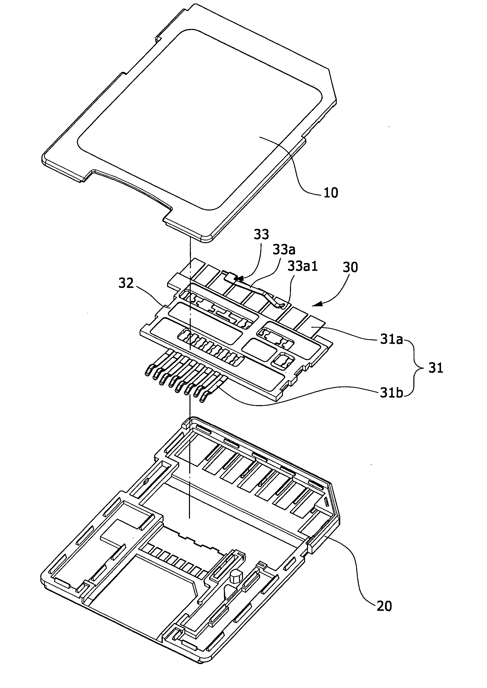
[0017] Referring to FIGS. 4 to 7, the present invention comprises an upper housing 10, a lower housing 20, and an adaptive terminal module 30, for adapting a Transflash memory card into an SD memory card. The adaptive terminal module 30 is composed of a plurality of terminals 31 and a moldbase 32 for fixing positions of the terminals 31, wherein the terminals 31 are formed with 9 SD pins 31a and 8 Transflash pins 31b at a front end and a rear end of the moldbase 32, respectively. Except that a third terminal is an independent SD pin 31a, the rest are long terminals 31 extending from the SD pins 31a to the Transflash pins 31b. Above the SD pins 31a of a sixth and a third terminals is installed with a bridge structure 33 which is a spring leaf 33a with one end being connected to a front end of the sixth SD pin 31a, and a power end 33a1 of the other end being located above the third terminal 31, or a bend piece 33b installed in an inner surface of the upper housing 10 with two power en...


PUM


Abstract

A transflash-to-SD adaptive card structure is composed of an upper housing, a lower housing, and an adaptive terminal module, to adapt a Transflash memory card into an SD memory card. The adaptive terminal module consists of a plurality of terminals and a moldbase for fixing positions of the terminals. The terminals are formed with 9 SD pins and 8 Transflash pins at a front end and a rear end of the moldbase, respectively. Above the SD pins of sixth and third terminals is installed with a bridge structure. Accordingly, after the adaptive terminal module is emplaced at a proper position between the upper and lower housings, the upper and lower housings are riveted and fixed by an ultrasonic wave, such that power ends of the bridge structure can be pressed down by the upper housing, thereby enabling the sixth terminal to be in contact with the third terminal for short-circuiting.

Description

BACKGROUND OF THE INVENTION [0001] (a) Field of the Invention [0002] The present invention relates to a Transflash-to-SD adaptive card structure, and more particularly to a bridge structure which is used for forming a short-circuiting between terminals in a Transflash-to-SD adaptive card, which will generate a contact short-circuit for two terminals that were originally not interconnected, so as to successfully transmit signals. [0003] (b) Description of the Prior Art [0004] As the popularity of 3C electronic consumer products, such as digital cameras, PDA (Personal Digital Assistant), and MP3 players, the development of flash memory cards becomes enriched as well, generating all kinds of memory cards with a variety of specifications. The most popular memory cards include SM (SmartMedia), xD-Picture Card, CF (CompactFlash), MD (MicroDrive), MS (Memory Stick), SD (Secure Digital), and MMC (MultiMedia Card). As the size of 3C digital products becomes smaller and smaller, memory cards ...

Claims


Application Information

Patent Timeline
Patent Type & Authority Applications(United States)
IPC IPC(8): H01R24/00
CPCH01R31/08H01R31/06
Inventor LEE, YUN-HSIU
Owner LEE YUN HSIU
Why Eureka
Try Eureka