System and method for designing a free form reflector

Active Publication Date: 2007-09-20
TSINGHUA UNIV +1
View PDF2 Cites 46 Cited by
  • Summary
  • Abstract
  • Description
  • Claims
  • Application Information

AI Technical Summary

Benefits of technology

[0010]A reflector profile of the present system is represented by a cubic NURBS curve. The coordinates of control points are used as variables, and a merit function specific to non-imaging reflector design is presented. The DE is performed to generate

Problems solved by technology

In addition, the crossover and mutat

Method used


Image

  • System and method for designing a free form reflector
  • System and method for designing a free form reflector
  • System and method for designing a free form reflector

Examples


Embodiment Construction

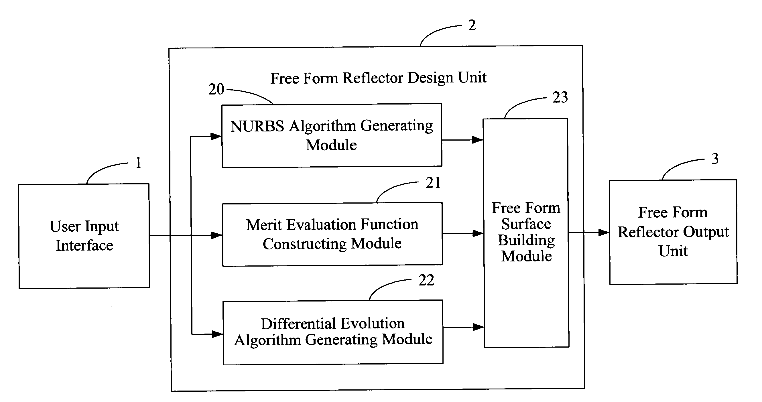
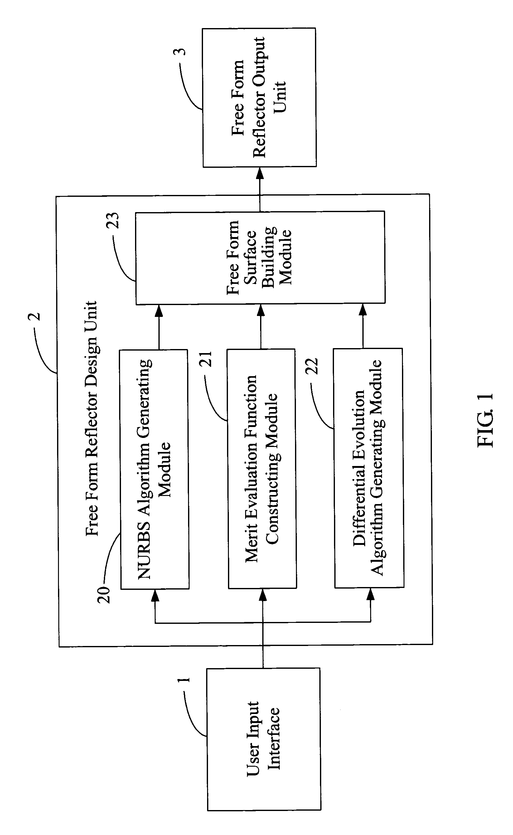
[0030]FIG. 1 is a schematic diagram illustrating a system for designing a free form reflector (hereinafter “the system”) in accordance with a preferred embodiment. The system mainly includes a user input interface 1, a free form reflector design unit 2 and a free form reflector output unit 3.

[0031]The user input interface 1 is configured for receiving various data associated with a desired free form reflector input by a user from an input device (e.g., a keyboard). The data typically include desired dimensions, desired illuminance distributions, and searching limits of the free form reflector.

[0032]The free form reflector design unit 2 installed in a computer is configured for generating an optimum free form surface according to the input data by performing a non-uniform rational basis splines (NURBS) algorithm, a merit evaluation function, and a differential evolution (DE) algorithm. The free form reflector design unit 2 includes an NURBS algorithm generating module 20, a merit eva...


PUM


Abstract

A system for designing a free form reflector includes a user input interface (1), a free form reflector design unit (2), and a free form reflector output unit (3). The user input interface is configured for receiving various data associated with a desired free form reflector, via an input device. The free form reflector design unit is installed in a computer and configured for generating an optimum free form surface according to the input data by performing a non-uniform rational basis splines (NURBS) algorithm, a merit evaluation function, and a differential evolution (DE) algorithm. The free form reflector output module is configured for generating a free form reflector according to the optimum free form surface and outputting the free form reflector, in the form of a computer-aided design (CAD) drawing, to a display and/or a printer. A related method is also disclosed.

Description

BACKGROUND OF THE INVENTION[0001]1. Field of the Invention[0002]The present invention generally relates to systems and methods for designing reflectors and, more particularly, to a system and method for designing a free form reflector.[0003]2. Description of Related Art[0004]Non-imaging reflectors are widely used in illumination and solar energy systems. In these applications, a non-imaging reflector is designed to convert the Lambertian source into a beam with a divergence of half-angle θ without loss of throughput. One direct design approach is to using algebraic methods, among which a tailored edge ray approach has made a great success. In this approach, a two-dimensional (2D) reflector is determined by reflector equations that are deduced from an edge-ray method and conservation of energy. For a three dimensional (3D) reflector design, it is common to solve the problem by reducing three dimensions to two dimensions. Thus, a 3D reflector can be generated by means of rotational or...

Claims


Application Information

Patent Timeline
IPC IPC(8): G06F17/50
CPCG06F17/50G06F2217/16G02B19/0033G02B19/0023G02B19/0019G06F30/00G06F2111/10
Inventor YANG, BOYAN, YING-BAIYANG, XING-PENGJIN, GUO-FAN
Owner TSINGHUA UNIV
Why Eureka
Try Eureka