Cleaning implement

a technology for cleaning implements and hard surfaces, applied in the direction of carpet cleaners, window cleaners, cleaning equipment, etc., can solve the problems of difficult to adapt devices for continued use, multiple devices are required, and difficult to remove, so as to facilitate cleaning, facilitate quick attachment and removal, and minimize evaporation from the substrate

Inactive Publication Date: 2007-09-27
BILLIG JASON C +3
View PDF24 Cites 27 Cited by
  • Summary
  • Abstract
  • Description
  • Claims
  • Application Information

AI Technical Summary

Benefits of technology

[0019]With some cleaning liquids it is desirable to cover the substrate, or a cartridge containing the substrate, between uses to minimize evaporation from the substrate. This can be achieved with a removable cover. That cover will also limit evaporation prior to the first use, albeit prior to the first use a sealed packet may be the preferred way to protect the cartridge.
[0020]In particularly preferred forms the support head is essentially triangular in cross section (most preferably isosceles triangular). This permits free rotation of the support on its axis for about 300 degrees of rotation. Additional rotation is prevented as the longer end of the triangle will contact a structure of the handle before further rotation can occur. This helps insure that the support head surfaces are optimally aligned with typical vertical surfaces being cleaned (e.g. a window).
[0021]Structures are also preferably provided to facilitate quick attachment and removal of the absorbent sheet(s). Each sheet can be provided with slots adjacent its ends which can hook onto corresponding projections on the support head. Some of the projections can be on a side of the support head that is pivotably mounted to another side. The attachment of the sheet(s) can be made when the sides are pivoted open and the sheet stack can then be dragged into a tight alignment by the closing of the sides.
[0022]The substrate is preferably mounted to a cartridge housing, with the cartridge housing being mounted to the support head and holding a plurality of additional substrate pieces in separate wells. Further, a portion of the substrate facing the surface to be cleaned can be segmented with non-porous barriers between the segments. These structures further facilitate cleaning while minimizing drool.

Problems solved by technology

Hence, several devices are required, and time is needed to shift from device to device.
However, with these devices once the liquid was used up or the collection capacity of the device exceeded, it was difficult to adapt the device for continued use.
Moreover, the devices were not compact and were unduly heavy.

Method used


Image

  • Cleaning implement
  • Cleaning implement
  • Cleaning implement

Examples


Embodiment Construction

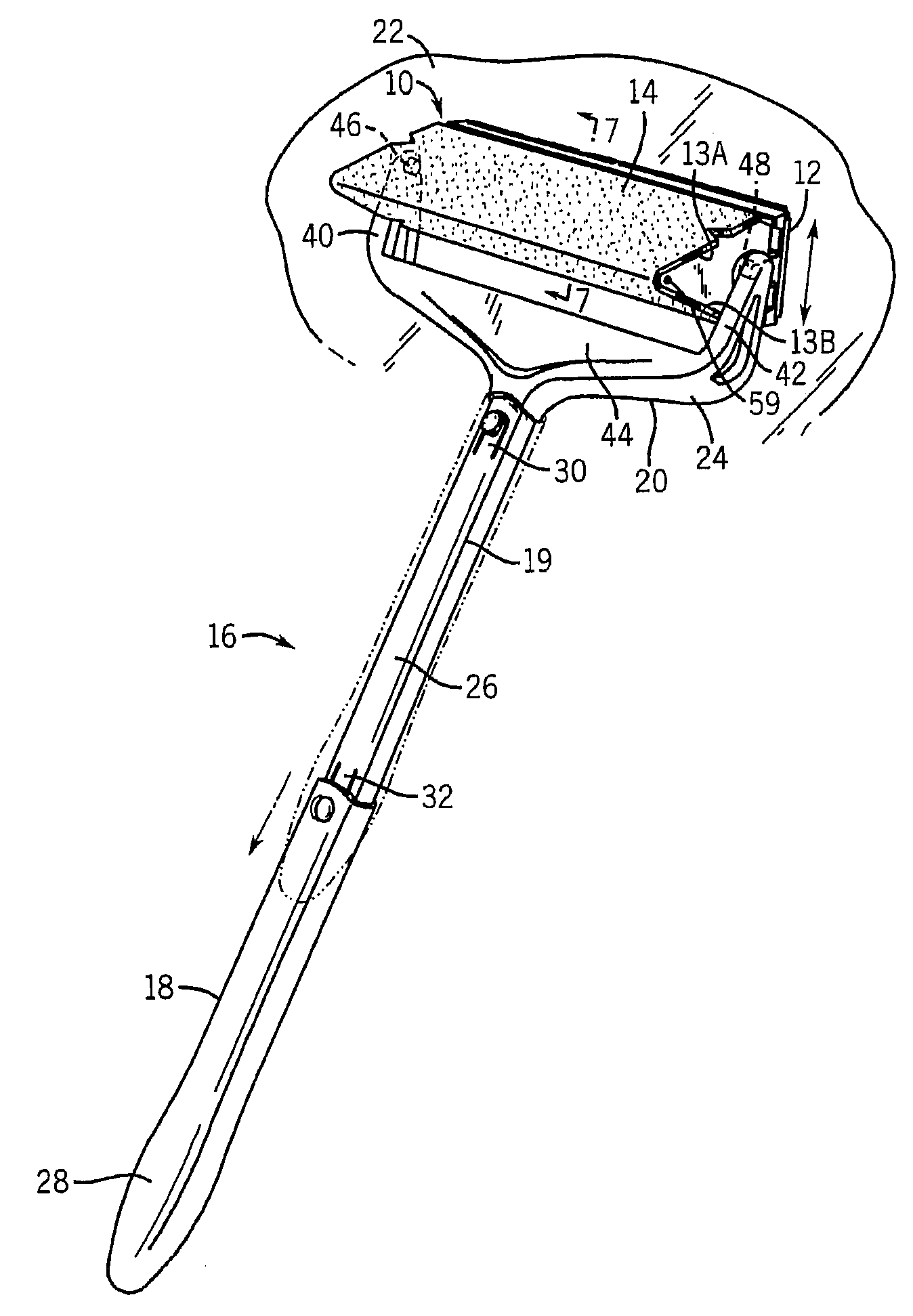
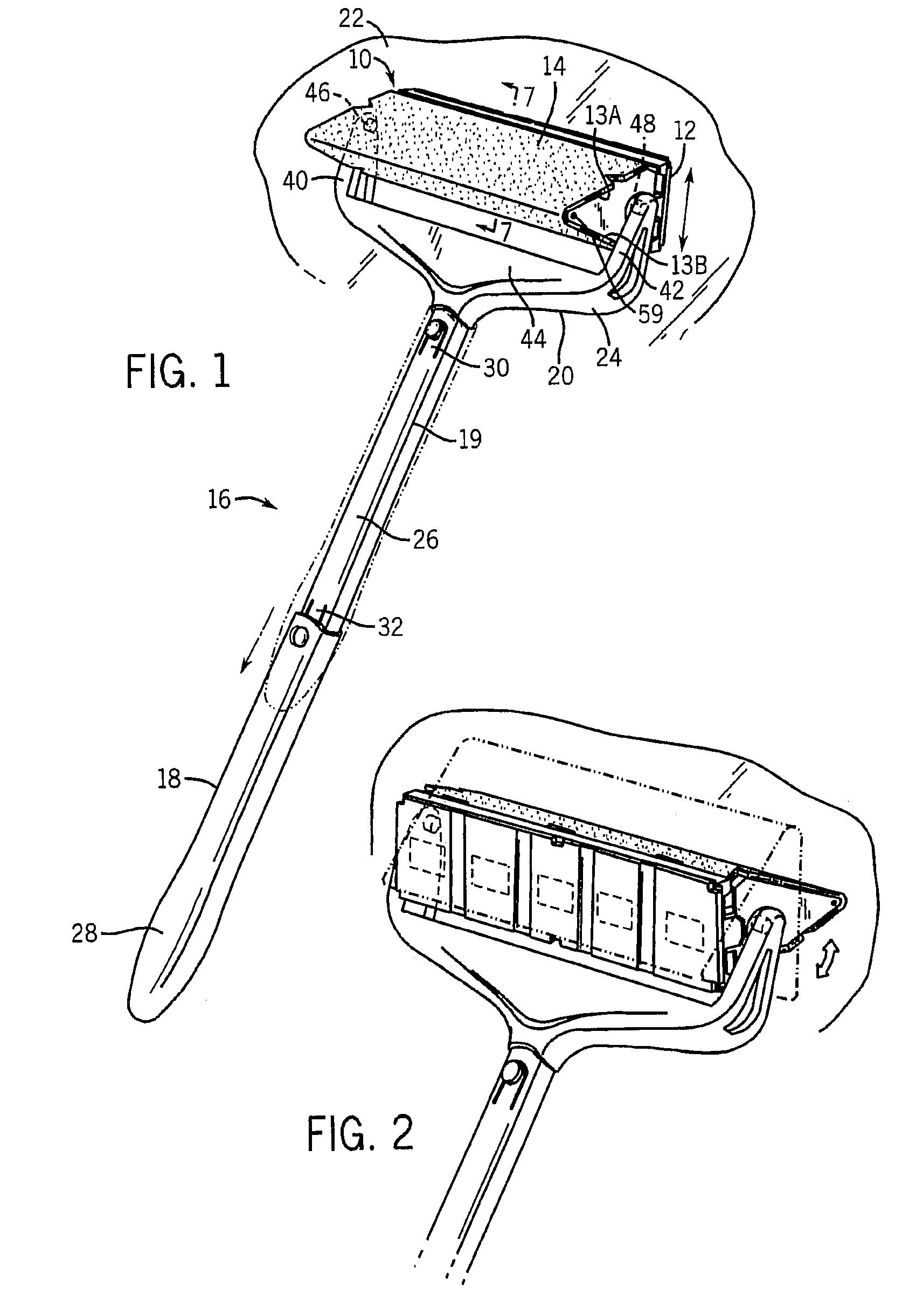
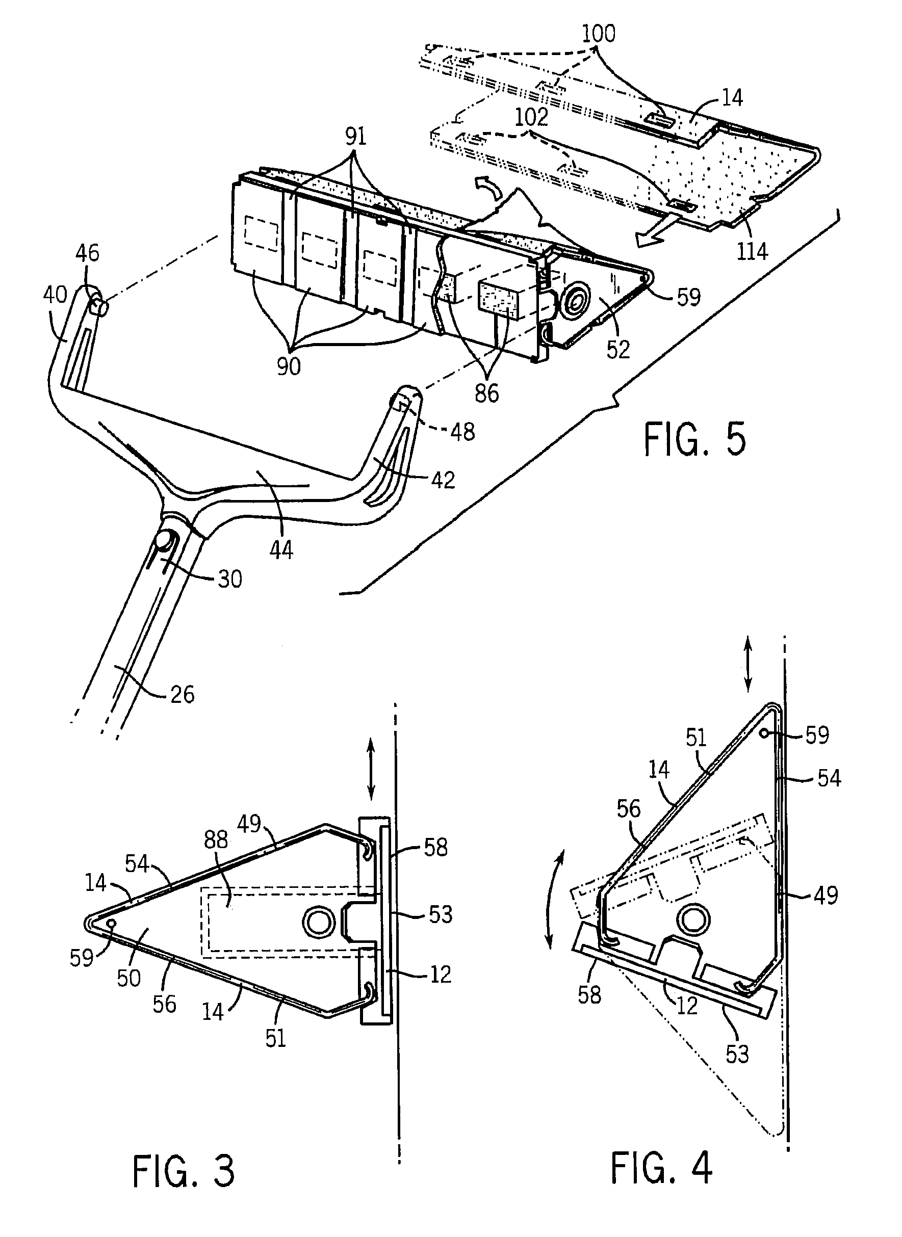
[0046]Turning first to FIGS. 1-4, a generally triangular cross section cleaning implement is shown having a support head (generally 10) with one side being a substrate 12 for applying a cleaning liquid, and two sides 13A / 13B being covered by a stack of absorbent tear-off sheets 14. There is also a handle structure (generally 16) having a lower end 18 and an upper end 19 linked to a fork 20.

[0047]The support head 10 is rotatably mounted between the arms 40 and 42 to align the impregnated substrate 12 with a surface to be cleaned (such as a window glass surface 22). When holding the handle lower end 18 the substrate 12 can be pressed against and dragged on the window glass surface 22, thereby applying cleaning liquid to the surface and to some extent scrubbing the surface to help remove stains and other deposits.

[0048]Next, the support head 10 can be rotated as shown in FIGS. 2 and 4 to align one of the tear-off sheet sides with the glass surface 22. A sheet 14 can then be pressed aga...


PUM


Abstract

A cleaning implement is disclosed that provides multiple functions useful in cleaning windows and similar surfaces. There is a support head that has three sides, one being a cleaning liquid applicator side and two presenting an absorbent sheet. The liquid applicator side can apply a cleaning liquid to a surface to be cleaned and optionally can provide scrubbing to the surface. The sheet can perform rough drying followed by finish drying, and/or other functions. Replacement liquid applicator cartridges and replacement sheets, or stacks of sheets, are also disclosed.

Description

CROSS-REFERENCE TO RELATED APPLICATIONS[0001]This application claims priority on U.S. provisional application 60 / 784,912, filed Mar. 22, 2006.STATEMENT REGARDING FEDERALLY SPONSORED RESEARCH / DEVELOPMENT[0002]Not applicable.BACKGROUND OF THE INVENTION[0003]The present invention relates to devices for cleaning windows and other hard surfaces. More particularly, it relates to “all-in-one” type devices that deliver a cleaning fluid, work the fluid along the surface being cleaned, and remove the used liquid.[0004]Cleaning of windows and other hard surfaces typically requires several tools and is a multi-step process. One typically picks up a spray bottle and spray the window, then picks up a sponge or cloth and works the cleaning fluid along the window glass, then picks up a squeegee, rag or other device to remove the used cleaning fluid. Hence, several devices are required, and time is needed to shift from device to device.[0005]U.S. Pat. No. 1,376,195 disclosed an all-in-one type windo...

Claims


Application Information

Patent Timeline
Patent Type & Authority Applications(United States)
IPC IPC(8): A47L1/06
CPCA47L1/08A47L13/22A47L13/12
Inventor BILLIG, JASON C.LESLIE, STUART M.CURTISS, CHARLES A.MALLARD, DAVID
Owner BILLIG JASON C
Why Eureka
Try Eureka