Air filter arrangement for an internal combustion engine

a technology for air filters and internal combustion engines, which is applied in the direction of machines/engines, combustion-air/fuel-air treatment, and separation processes, etc., can solve the problems of insufficient fuel and combustion air supply to the internal combustion engine, and achieve the effect of improving the filling, good degree of filling of the channel, and prolonging the channel length

Active Publication Date: 2007-09-27
ANDREAS STIHL AG & CO KG
View PDF9 Cites 10 Cited by
  • Summary
  • Abstract
  • Description
  • Claims
  • Application Information

AI Technical Summary

Benefits of technology

[0018]The shield advantageously extends the mixture channel and the air channel up to the communication opening. At low speeds, often insufficient fuel and combustion air can be supplied to the internal combustion engine. It has been shown that for an adequate filling of the air channel and of the mixture channel, the channel lengths that are available are critical. An extension of these channels effects an improvement of the filling, whereby in particular resonance characteristics of the channels should also be taken into account. Due to the fact that the mixture channel and the air channel are extended by the shield, it is possible to achieve extended channel lengths in a simple manner where the installation space is small. By the provision of the communication opening in the shield, it is possible to achieve a coordination of the channel lengths. As a result, it is also possible to adapt an air filter arrangement to an internal combustion engine simply by exchanging the shield. It is also possible in a straightforward manner to achieve a good degree of filling of the channels, and an adequate supply of the internal combust ion engine with fuel and combustion air.
[0019]The shield advantageously has a bulged portion that extends over the inlet opening of the mixture channel. Fuel that has passed over out of the mixture channel can collect in the bulged portion, and from there can again be guided back into the mixture channel via the combustion air that is drawn in. The shield advantageously has a channel-like connecting portion that extends from the inlet opening of the mixture channel to the inlet opening of the air channel, and by means of which the air channel and the mixture channel are interconnected. The connecting portion ensures that at low spe...

Problems solved by technology

At low speeds, often insufficient fuel and combusti...

Method used


Image

  • Air filter arrangement for an internal combustion engine
  • Air filter arrangement for an internal combustion engine
  • Air filter arrangement for an internal combustion engine

Examples


Embodiment Construction

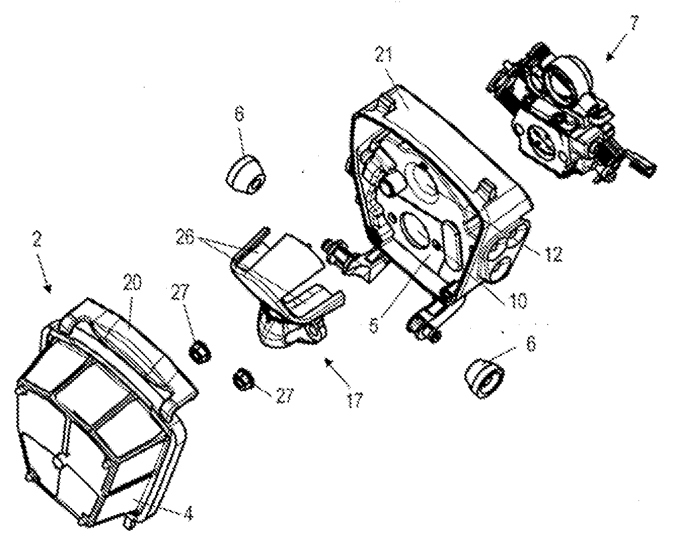
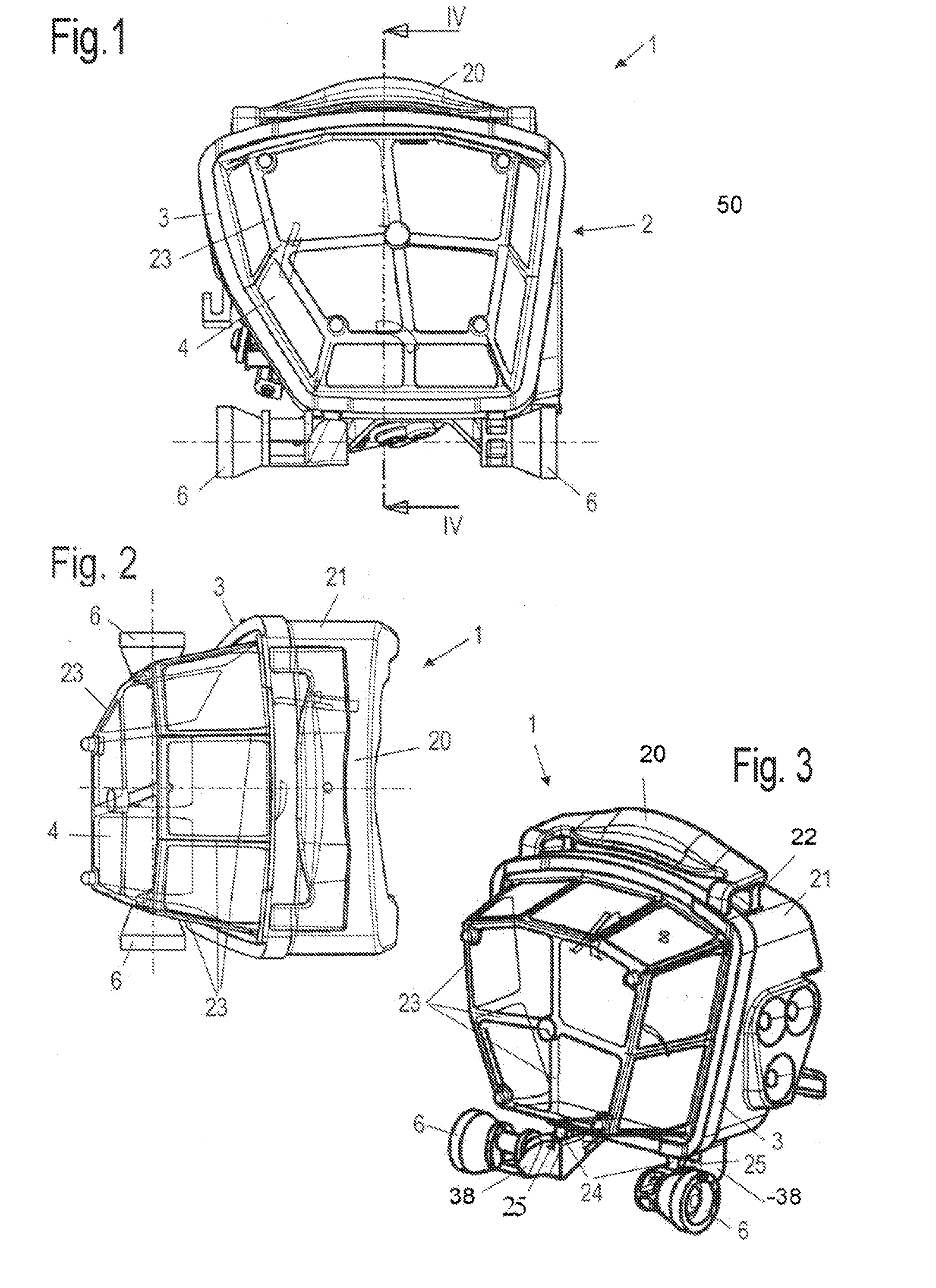
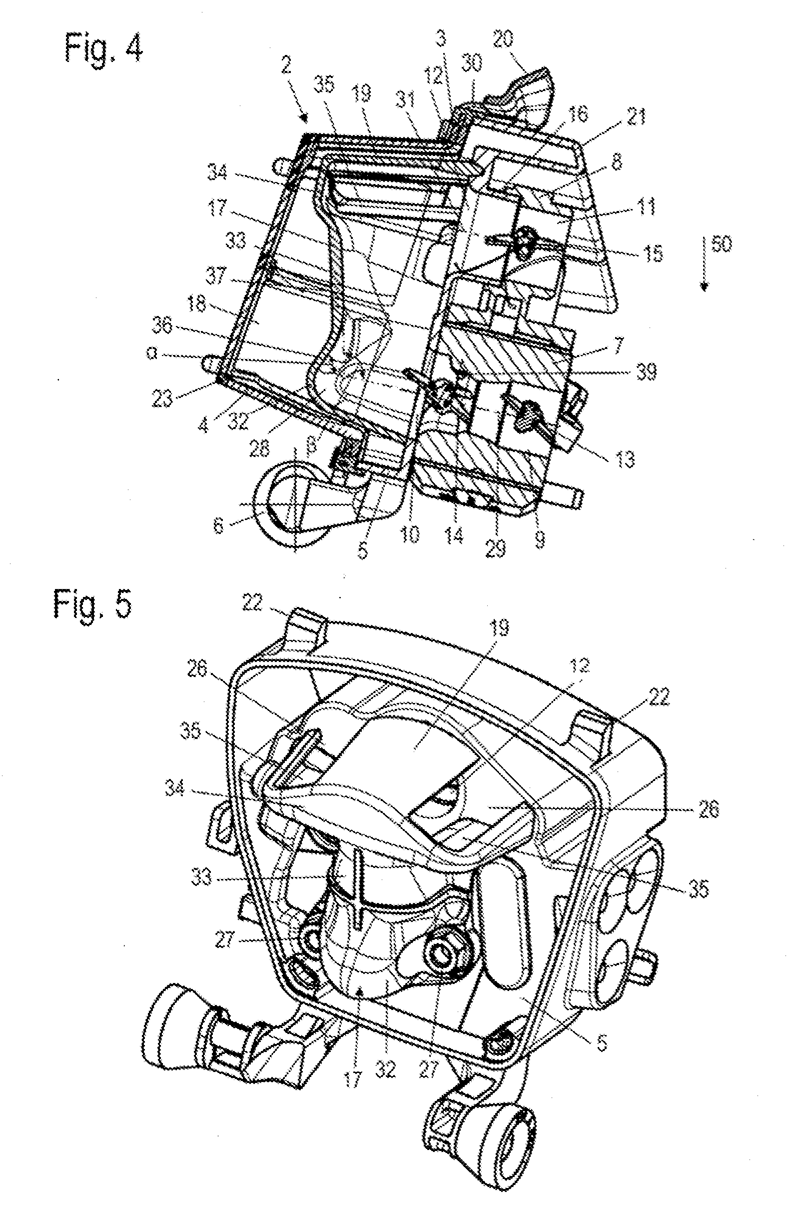
[0023]Referring now to the drawings in detail, FIGS. 1 to 3 show an air filter arrangement 1 for an internal combustion engine, especially for a two-cycle engine in a manually guided implement such as a power saw, a cut-off machine a brushcutter, or the like. The air filter arrangement 1 comprises an air filter 2 having an air filter frame 3 on which is disposed a filter element 4. The filter element 4 spans the flat air filter frame 3 in a dome-like manner, and is supported on struts 23, which form a lattice, the lattice openings of which are covered by the filter element 4.

[0024]Disposed on the air filter frame 3 is a grip element 20 that cooperates with snap-fit connectors 22 on the air filter housing 21. On the opposite side of the frame 3 tabs 24 are provided on the frame 3 that extend into receiving means 25 formed on the air filter housing 21. The air filter 2 is fixed on the air filter housing 21 by means of the tabs 24 and the grip element 20. By releasing the latching or e...


PUM

PropertyMeasurementUnit
Forceaaaaaaaaaa
Gravityaaaaaaaaaa

Abstract

An air filter arrangement for an internal combustion engine, especially for a two-cycle engine in a manually guided implement such as a power saw, a cut-off machine, etc., and including an air filter element that delimits a first clean chamber. The air filter arrangement has an inlet opening for an air channel and an inlet opening for a mixture channel. A shield is provided for shielding the air filter element relative to the mixture channel. The inlet opening of the air channel and the inlet opening of the mixture channel are interconnected via the shield.

Description

[0001]The instant application should be granted the priority date of Mar. 24, 2006 the filing date of the corresponding German patent application 10 2006 013 602.0.BACKGROUND OF THE INVENTION[0002]The present invention relates to an air filter arrangement for an internal combustion engine, in particular for the two cycle engine of a manually guided implement such as a power saw, a cut-off machine, or the like.[0003]U.S. Pat. No. 6,328,288 B1 discloses a carburetor having an air filter, with a mixture channel and an air channel opening out at the base of the air filter. U.S. Pat. No. 5,503,649 A furthermore discloses disposing shield elements between the inlet opening of the mixture channel and the filter element for retaining fuel that pulses back out of the mixture channel, thus preventing contamination of the air filter.[0004]With air filter arrangements where an air channel and a mixture channel communicate with the clean chamber of the air filter, the channels are customarily di...

Claims


Application Information

Patent Timeline
IPC IPC(8): B01D50/00
CPCF02M35/024F02M35/1019F02M35/1017Y10S55/30Y10S55/28
Inventor DIEPOLDER, DANIELBOHNAKER, EBERHARDJENSEN, ARNE
Owner ANDREAS STIHL AG & CO KG
Why Eureka
Try Eureka