
Illuminated Hummingbird Feeder

Inactive Publication Date: 2007-09-27
RICHMOND SIMON NICHOLAS
View PDF20 Cites 45 Cited by
  • Summary
  • Abstract
  • Description
  • Claims
  • Application Information

AI Technical Summary

Benefits of technology

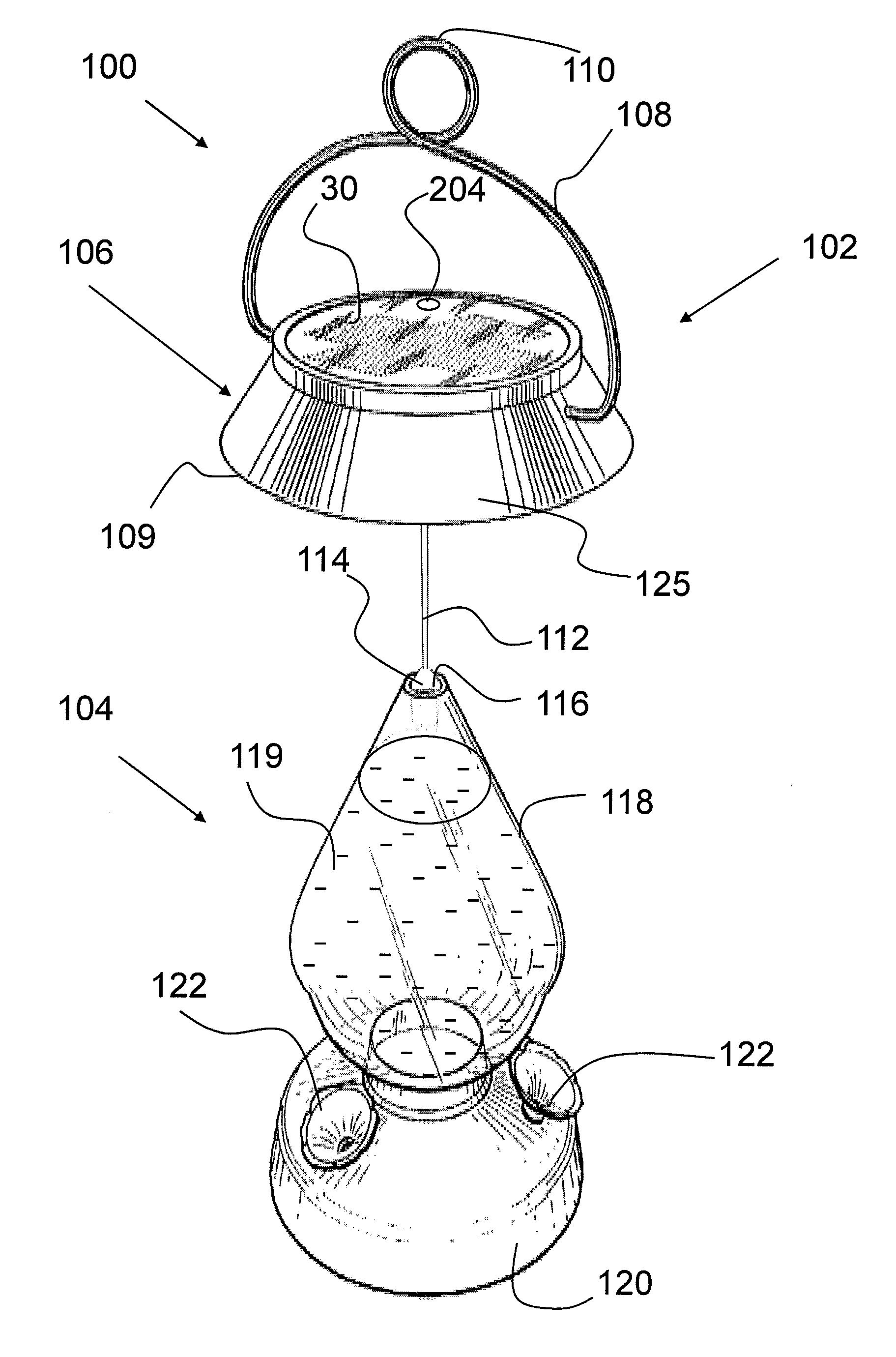
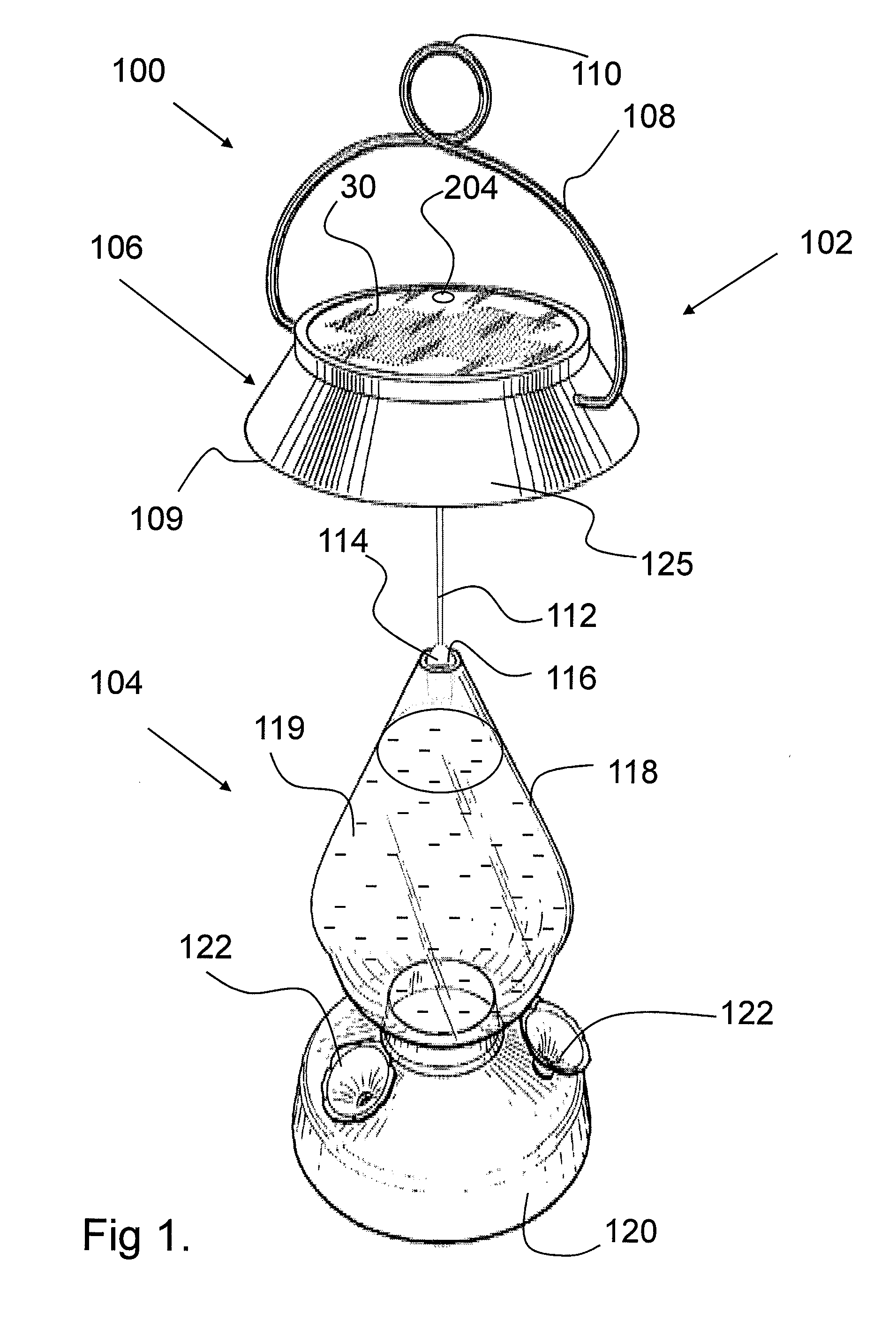
[0023] Briefly describe, it would be desirable to provide an illuminated hummingbird feeder which provides a different nighttime aesthetic appearance, as well as providing all the ease of use and cleaning of a non-electrically illuminated hummingbird feeder.
[0025] The aforementioned illumination effect is achieved by providing a hummingbird feeder having a rechargeable electrical power source and a solar energy system that collects solar energy, converts it into electrical energy, uses the electrical energy to recharge the rechargeable electrical power source, uses the electrical power source to power a light source which illuminates a liquid food source contained with the feeder so the liquid food source illuminates and is visible in low light conditions. It is also achieved by a novel releasable solar powered illumination assembly system to facilitate maintenance.
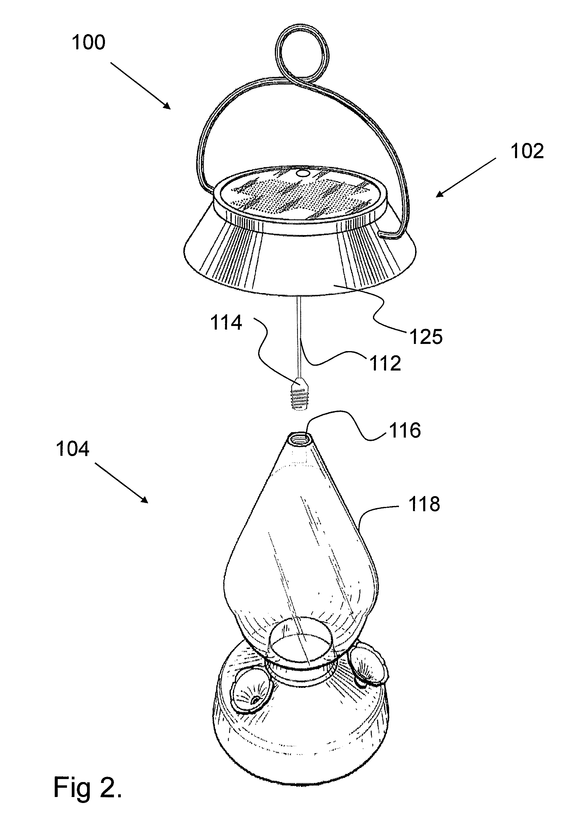
[0026] The solar powered bird feeder according to the present invention provides significant advantages, including: (1) the rechargeable electrical power source can be recharged by the solar energy system; (2) the lighting element allows the level of the food liquid in the hummingbird feeder to be monitored at night; and (3) the releasable solar electronics module facilitates easy and regular washing of the feeder parts. These and other features, objects and advantages of the present invention will be evident from the will be more fully understood by references to the following drawings and detailed description of the invention.

Problems solved by technology

Thus the prior art does not disclose a bird feeder that illuminates throughout the food reservoir.
However, many people return home from work after dark.
On an evening when a user cannot readily determine the solution level in the feeder and thus if the feeder needs refilling, the need is not readily apparent in the dark.
Attempts to solve this problem have generally been based around simply increasing the food reservoir size but such an approach is not always practical as the solution has a tendency to spoil rapidly.
With seed based feeders, the various birdseed types have varying volume-to-weight ratios so it may be difficult to establish a universal “almost empty weight” for a seed feeder.
However, it is dark at that time and thus not suitable for the owner of a feeder to view the hummingbird feeding.
Some bird feeders use a phosphorescent glass food reservoir to provide some low level of illumination for a few hours at dusk, however, such a method of illumination does not visibly and clearly illuminate a liquid feed solution.
This is often inconvenient as the feeder may be located at an impractical distance from an electrical outlet.
Alkaline batteries are economical but require frequent replacement which may be inconvenient for the owner.
Attempts have been made to circumvent this problem by making disposable hummingbird feeders but this is uneconomical and wasteful.
One problem that exists with solar illuminated hummingbird feeders is the electrical parts that create the solar illumination are not usually suitable for water immersion.
Unfortunately, the foliage or the branch itself may partially restrict the amount of sunlight or light energy from reaching the top of the bird feeder or lighting device and thus the solar panel.
As a result, solar panels on the top of the light device or birdfeeder do not receive adequate sunlight to fully charge their batteries and fail to provide illumination of adequate duration.
Unfortunately, the housings are the bulkiest and most expensive parts to send by freight but this has been the practice because the solar and electronic parts are integrally assembled into the housings.
Further, many lighting and birdfeeder housings have different shaped and sloped regions on their top portions which makes some designs not suitable for locating solar panels thereon and those designs are not produced as solar products.
This results in some designs not being produced with solar functions and results in many different shaped and sized solar panel components that must be ordered from the solar panel producers.
If the panel is sized with a larger charging capacity, the battery may be fully charged earlier and then the extra power generated by the panel is wasted.
If the panel is sized with a smaller charging capacity, the battery may not be fully charged and might not illuminate the light source connected to the battery for the duration of time the light source was intended to illuminate.
Since the solar panel is a major cost component of a solar landscape light, manufacturers have a problem in determining an optimal charging capacity of solar panel that finds a balance between insufficient operating hours with a lower cost i.e. and expensive wasted solar power generation.
Further, there are factors that are outside the control of the manufacturer of the solar light that affect the number of daily hours and strength of direct sunlight received by the solar panel.
Accordingly, there are situations where the solar light may not be fully charging the battery when located at its installed location by the user.
When installed, in some situations, for example, where a plurality of solar landscape lights have been installed in a garden, there may be some light fixtures that are receiving adequate sunlight and some that are receiving inadequate sunlight.
Further, as the seasons change some installed lights may not be receiving sufficient light for the solar panel to fully charge the battery.

Method used


Image

  • Illuminated Hummingbird Feeder
  • Illuminated Hummingbird Feeder
  • Illuminated Hummingbird Feeder

Examples


second embodiment

[0090]FIG. 5 is a cross-sectional view of an unassembled food reservoir 602 for a solar powered illuminated hummingbird feeder in accordance with the present invention. It shows the unassembled food reservoir 602 comprising an upper neck portion 610 that contains a socket receiving cavity 612, a reservoir portion 604 substantially enclosing a cavity 606, and an aperture 608. The unassembled food reservoir 602 is constructed from a hand-blown glass with the neck portion added and the aperture drilled out as second and third manufacturing operations respectively. Alternatively, there may be no socket receiving cavity 612 but instead the socket housing module 116 of FIG. 4 may be integrally formed with the neck portion 610. The food reservoir 602 is an elongated substantially cylindrically shaped container for housing liquid hummingbird feed solution. Other geometric shapes and sizes, as well as shapes in form of animals and flowers, of different colors for the solution reservoir are p...

third embodiment

[0125]FIGS. 8A and 8B are schematic and cross-section views of a suspendible solar powered lighting assembly 800 in accordance with the present invention. The suspendible solar powered lighting assembly 800 comprises a lighting module 114, suspension wires 112 between the lighting module 114 and an operative components compartment 802 containing control circuitry and a rechargeable power source, suspension wires 808 between the compartment 802 and at least one suspended solar panel 815. The operative components compartment 802 contains rechargeable batteries 124 which are vertically oriented. The operative components compartment 802 is preferably suspended from a central hanging point. The batteries 124 are preferably recharged by two substantially vertically oriented substantially parallel and outwardly facing amorphous silicon solar panel 815 located at the end of a suspension assembly 800 suspended by electrical wires 808 from the an operative components compartment 802. In the e...

fourth embodiment

[0140]FIG. 10A is a schematic view of a solar powered illuminated hummingbird feeder 872 in accordance with the present invention. The present embodiment is an alternative hummingbird feeder design to the design disclosed in FIG. 9B. In the present embodiment there is a feeding assembly 870 which comprises a cap assembly 876 with an integral moat design which carries a hanging ring 878 which together provide support means and ant deterrent features for the feeder. The cap assembly 876 is preferably releasably attached to a liquid food reservoir 874 containing a nectar-like liquid food source 119, a covered feeding bowl assembly 882, a perch portion 880 and feeding stations 884. Attached to an at least partially light transmissive lower portion of the covered feeding bowl assembly 882 of the feeding assembly 870 is an illumination source. Suspended below the lighting module 114 is the previously suspendible solar powered lighting assembly 800 of FIG. 8A. Together these comprise an il...


PUM


Abstract

A hummingbird feeder includes a solar panel power source for illuminating a reservoir of liquid hummingbird food so that the hummingbird can find it at night. The solar panel itself preferably hangs below the feeder in a flexible manner so that it can collect the maximum amount of sunlight and swing in the breeze. An LED attached to the solar power source is positioned to illuminate the liquid reservoir from within the reservoir. The parts that comprise the feeder are easily disassembled for washing and cleaning.

Description

CROSS REFERENCE TO RELATED APPLICATIONS [0001] This application claims the benefit of and is related to U.S. Provisional Patent Application 60 / 811,137 filed on Jun. 5, 2006 by Simon N. Richmond entitled “Illuminated Hummingbird feeder” and claims priority to and is a Continuation-In-Part of U.S. patent application Ser. No. 11 / 303,247 filed on Dec. 16, 2005 by Simon N. Richmond entitled “An Illuminated Wind Chime”, and claims priority to and is a Continuation-In-Part of U.S. patent application Ser. No. 11 / 420,160 filed on May 24, 2006 by Simon N. Richmond entitled “A Solar Powered Fluorescent Gazing Globe”, the entire contents of all three applications are hereby incorporated by reference.BACKGROUND OF THE INVENTION [0002] 1. Field of the Invention [0003] This application relates generally to hummingbird feeders and, in particular, to hummingbird feeders having solar-powered internal illumination of an aqueous nutrient solution for feeding at night. [0004] 2. Description of Related A...

Claims


Application Information

Patent Timeline
IPC IPC(8): A01K7/00
CPCA01K39/012A01K39/026A01K39/0206
Inventor RICHMOND, SIMON NICHOLAS
Owner RICHMOND SIMON NICHOLAS
Learn More