Self powered pelletized fuel heating device

a heating device and self-powered technology, applied in the direction of domestic stoves or ranges, ways, fire safety failures, etc., can solve the problems of adding to the cost of the control system, and achieve the effect of reducing the cost of such redundant systems, good engineering design, and removing objections to external power source requirements

Inactive Publication Date: 2007-09-27
LANDON RICHARD BENSON
View PDF9 Cites 69 Cited by
  • Summary
  • Abstract
  • Description
  • Claims
  • Application Information

AI Technical Summary

Benefits of technology

[0017] Another objective of this invention is a self-contained power unit that is both functional, reliable and of an assembly using few parts and good engineering design. In this embodiment, the self-contained power unit charges a typical 12 VDC system wherein all controls, fans, blowers and feeder systems operate. There are no hybrid-powered circuitry requirements; thereby, reducing costs for such redundant systems. There are no external power requirements; therefore, no additional house wiring is required. In the preferred embodiment, the customers objections to external power source requirements are removed. An objective of this invention is to provide the convenience of a pellet stove with the independence of a wood stove.

Problems solved by technology

Some operations may need to be controlled differently, since the 12 VDC backup system may not handle some power requirements, such as the lighting / ignition requirements as mentioned above.
All the above mentioned complexities add to the cost of the control system.

Method used


Image

  • Self powered pelletized fuel heating device
  • Self powered pelletized fuel heating device
  • Self powered pelletized fuel heating device

Examples


Embodiment Construction

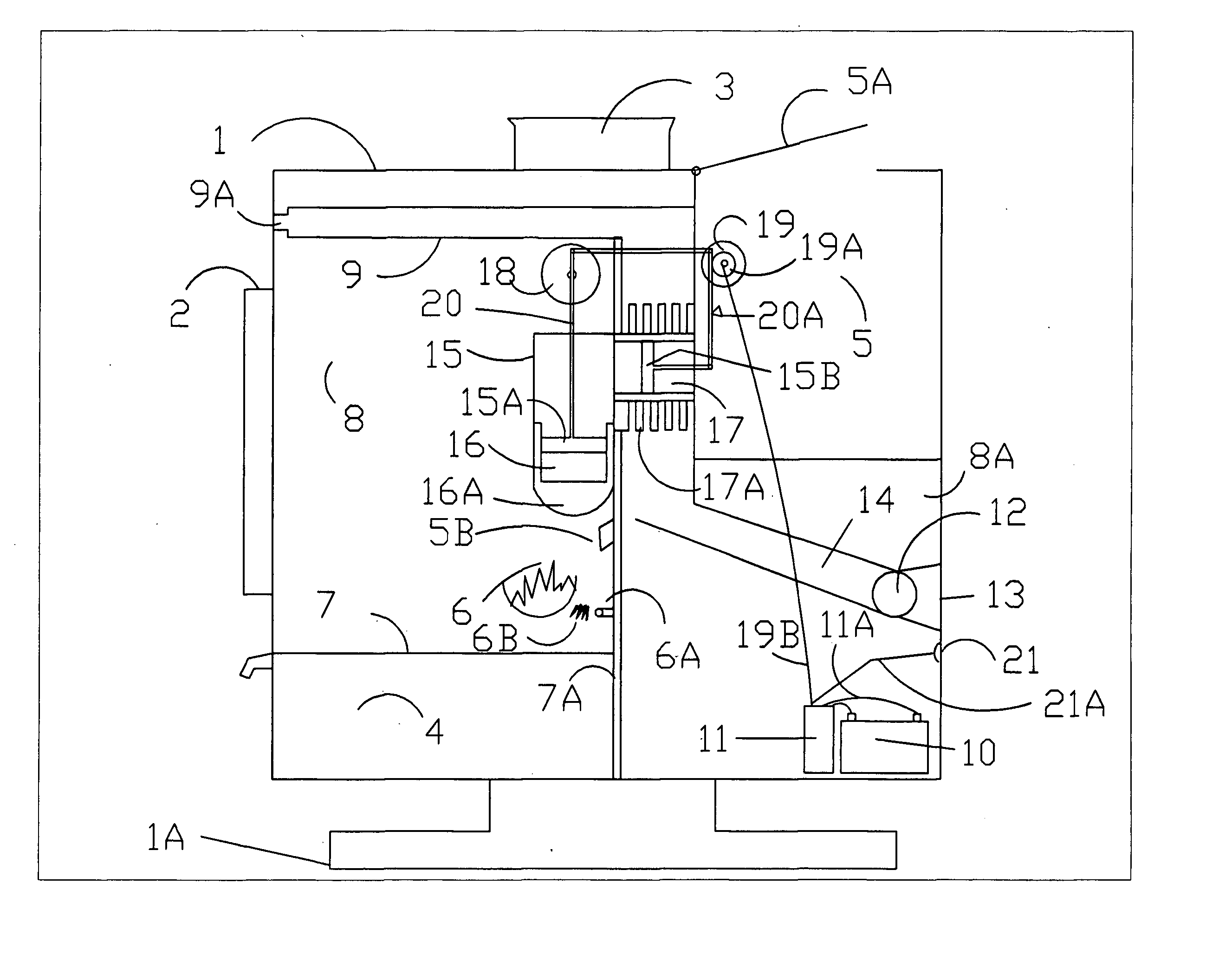
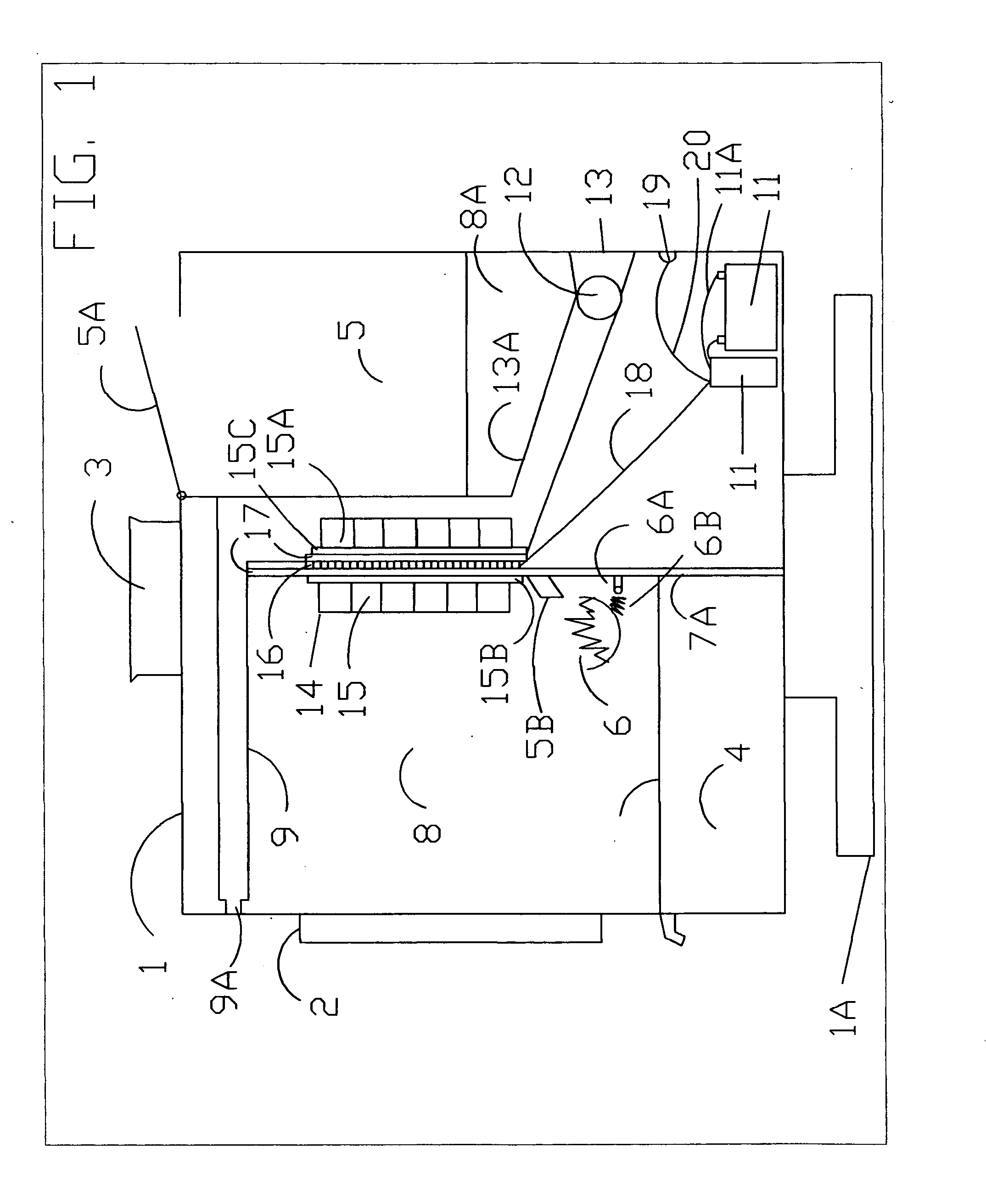
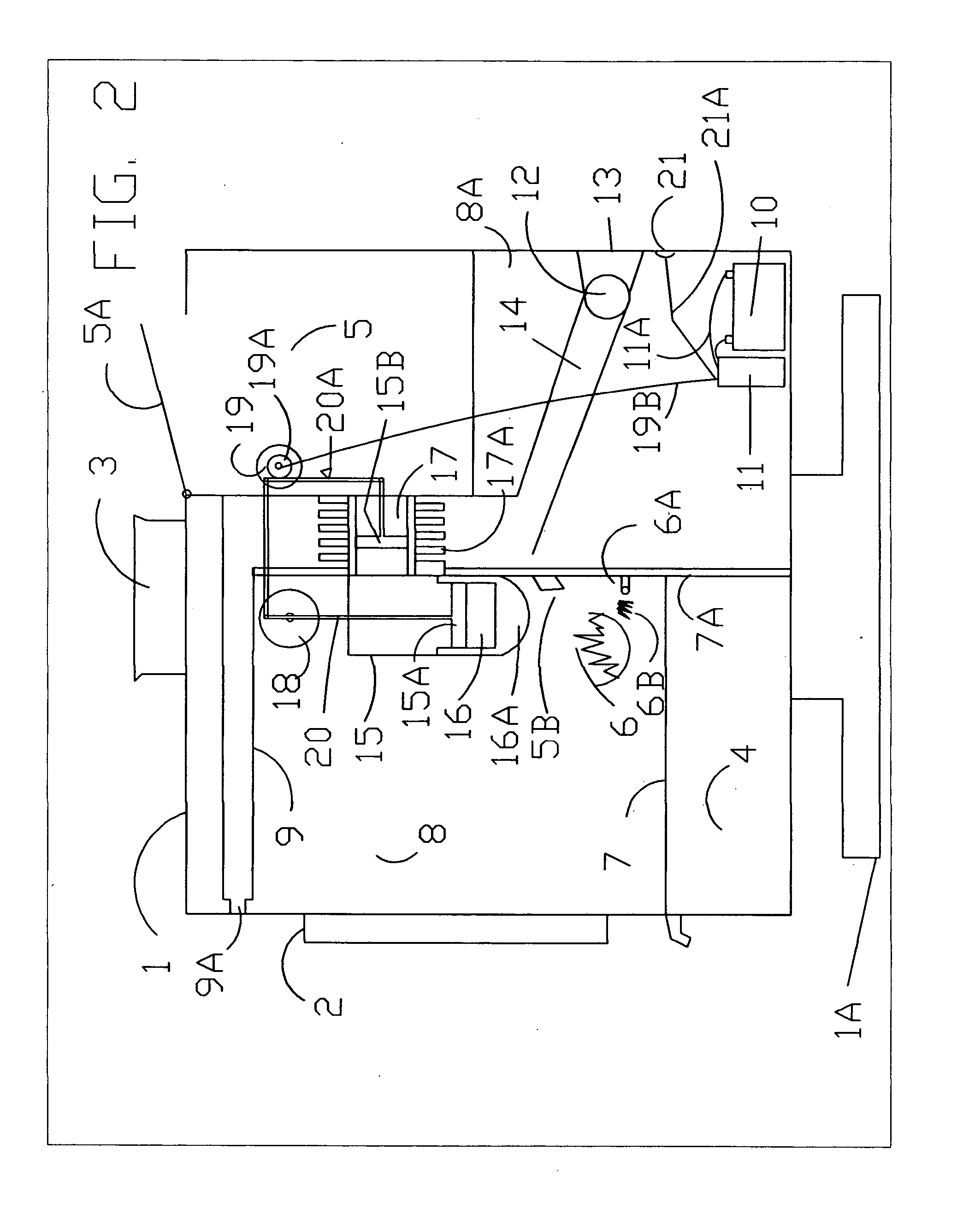
[0021] Turning to FIG. 1, there is illustrated a TEG pellet stove in the spirit of the invention. Typical of conventional pellet stoves in a stand-alone configuration, the illustration points out a body (1) and a stand (1A) supporting the body. It should be noted that an insert pellet stove will not have a stand but a flange covering the outside and sealing the unit to the surface of the fireplace once installed. In the spirit of the invention, typical pellet stoves, both stand-alone and insert, are utilizing a TEG unit as described in these preferred embodiments.

[0022] Turning again to FIG. 1, some of the typical pellet stove components are shown such as, a burn chamber door (2), a vent exhaust port (3), a removable ash collection tray (4), a pellet fuel reservoir (5), a pellet feed port (5A), a fire bowl burn area (6), an ignition and burn air port (A), an ignition element (6B), an ash grate (7), an insulated firewall (7A), a burn chamber (8), a cold chamber, a heat exchanger (9)...


PUM


Abstract

A self powered pelletized fuel heating device comprising a thermal electric generator (TEG) unit therein powering a typical collection of low voltage system components including a storage power unit. Non-typically, the heating device requires no external power supply and relies on thermodynamic principles using the pelletized fuel as a heat source. The TEG is configured and positioned optimally for conventional operation and installation requirements without modification to normal form or function.

Description

FIELD OF INVENTION [0001] The invention as disclosed here within consists of a pellet burning device for living / working area heating purposes. This device, also called a bio-mass burner, utilizes a thermoelectric generator (TEG) allowing the device to charge a self-contained battery system, thereby providing a stand-alone energy / heating system not requiring an external power source. The TEG pellet stove provides for both convenience and utility best reflected, but so far limited in present-day hybrid pellet stove heating units running a 12 VDC backup system for uninterrupted power supply function. Long power outages typical for many rural parts of the country prevent successful heating using conventional art. BACKGROUND OF INVENTION [0002] The typical pellet burning device is a heating stove configured to stand freely within the room, venting through an exposed pipe or configured as an insert to fit snugly inside a fireplace, venting through the existing chimney. These pellet stoves...

Claims


Application Information

Patent Timeline
Patent Type & Authority Applications(United States)
IPC IPC(8): F24B1/18
CPCF23B50/12F23M2900/13003F23M2900/13004F23M20/00F23N2039/02F24B1/024F23N2031/02F23N2231/02F23N2239/02
Inventor LANDON, RICHARD BENSON
Owner LANDON RICHARD BENSON
Why Eureka
Try Eureka