Rotary structure for display base docks

a technology of base docks and rotating structures, which is applied in the direction of machine supports, instruments, cabinet/cabinet/drawer, etc., can solve the problems of reducing affecting the use of base docks, and unable to provide swivel functions, etc., to save material consumption and reduce production costs.

Inactive Publication Date: 2007-09-27
TAIWAN THICK FILM IND
View PDF4 Cites 9 Cited by
  • Summary
  • Abstract
  • Description
  • Claims
  • Application Information

AI Technical Summary

Benefits of technology

[0011] The primary object of the present invention is to solve the aforesaid disadvantages. The invention provides a rotary structure for display base docks that has simplified elements and can save material consumption and reduce production cost.

Problems solved by technology

Hence the bracing dock does not provide swivel function.
However, as the display device becomes bigger and heavier, altering the viewing angle of the entire display device becomes more difficult.
However those base docks still have problems in use, notably: 1.
Installing the screen base seat on the rotary base dock is tedious and requires a great deal of manpower.
Material management and fabrication and assembly are difficult.
The rotary base dock is quire bulky and against the prevailing trend that demands lean and light.
It also requires a lot of materials and the cost is higher.
The rotary base dock cannot distribute the weight of the display screen evenly.
It is not stable and requires more efforts from users when in use.
The power cord or signal line tends to be dislocated or entangled in the event of improper operation.
Line fracture could happen and result in the risk of fire breakout and severe safety concern.

Method used


Image

  • Rotary structure for display base docks
  • Rotary structure for display base docks
  • Rotary structure for display base docks

Examples


Embodiment Construction

[0019]

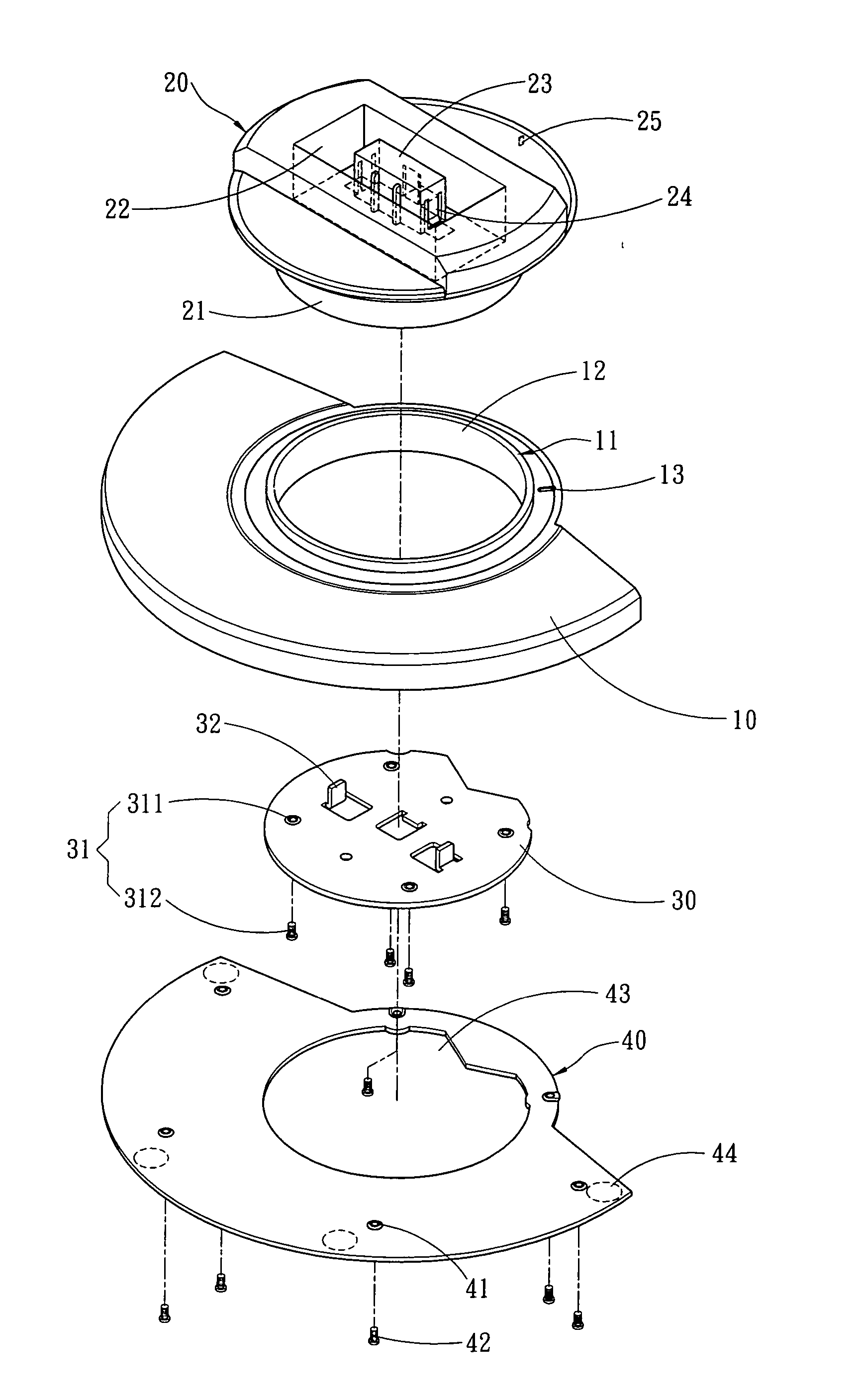
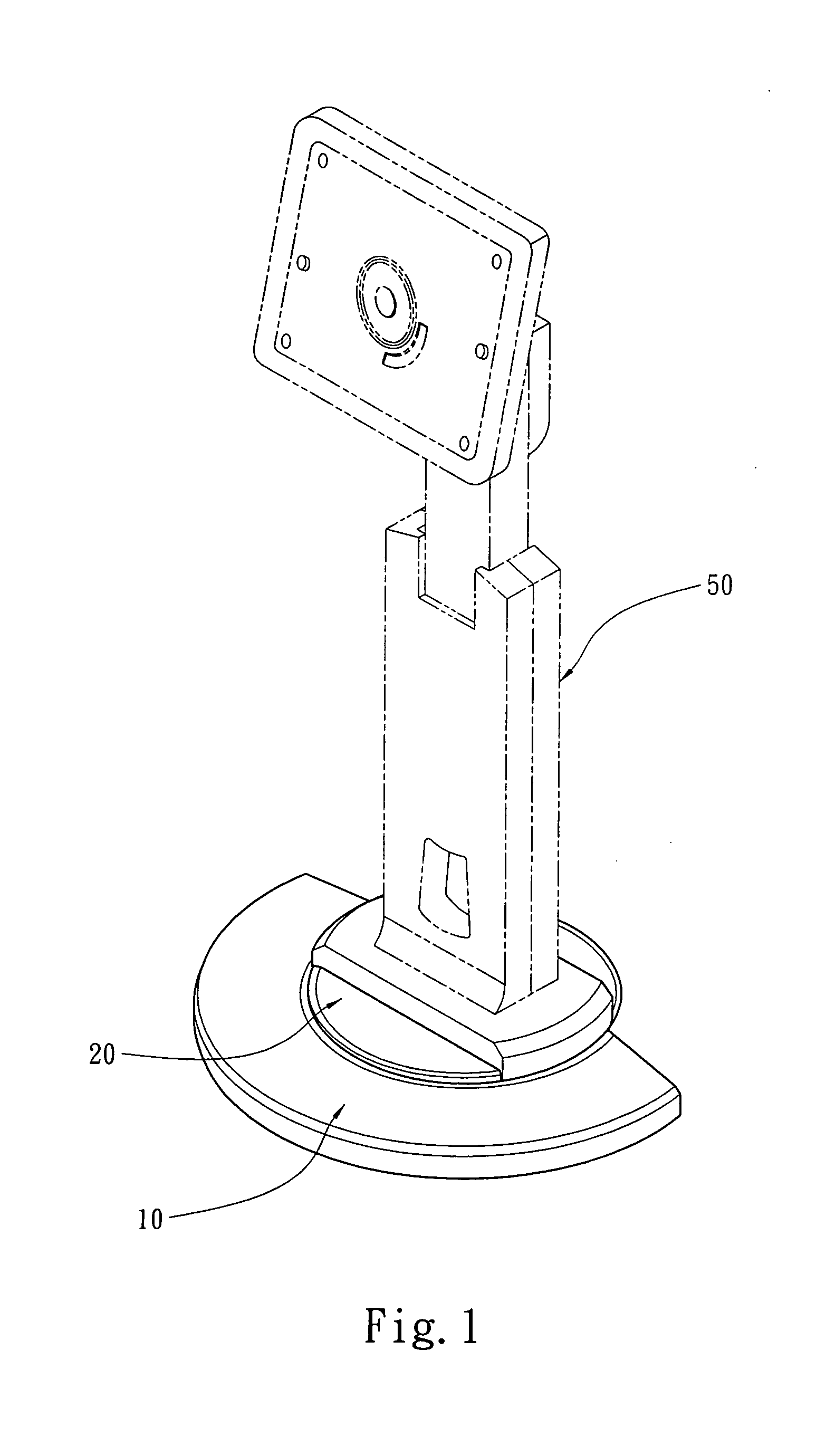
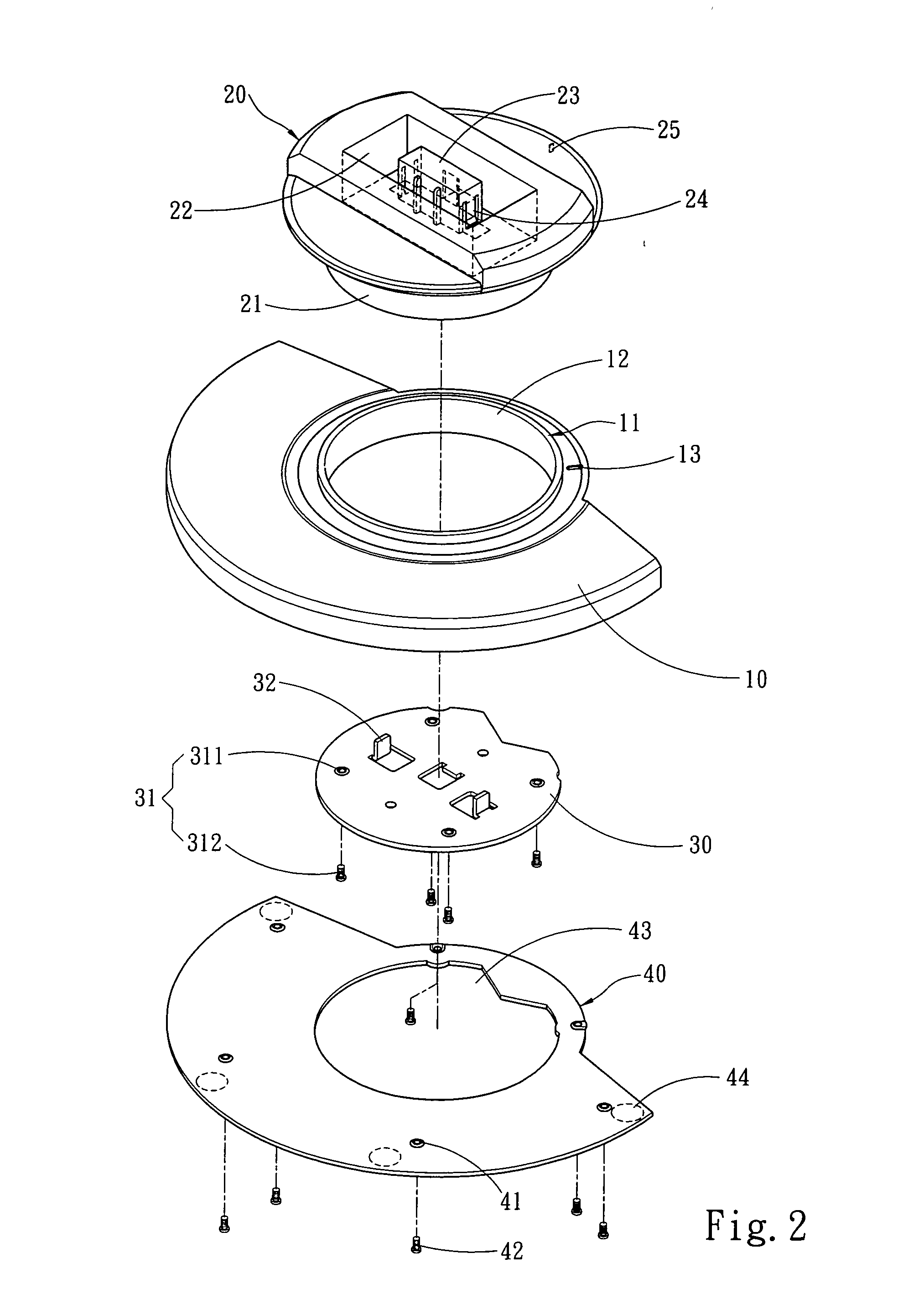
[0020] Please refer to FIGS. 1, 2 and 3, the rotary structure for display base docks of the invention includes a bracing seat 10 which has a confining zone 11. The confining zone 11 has an opening 12. There is a rotary dock 20 on one end of the opening 12. The rotary dock 20 has a fastening trough 22 which has an anchor boss 23 to hold a rack 50 to brace a display device (not shown in the drawings). The anchor boss 23 has a harness blade 24 which is elastic and anchored on the rack 50. The anchoring condition of the harness blade 24 on the rack 50 can be released under a force. The rotary dock 20 further has a coupling portion 21 inserting into the opening 12. There is a confining plate 30 on the other end of the opening 12. The confining plate 30 has an anchor lump 32 running through the coupling portion 21 to be fastened to the rack 50. The confining plate 30 further has an anchor member 31 to be fastened to the coupling portion 21. The anchor member 31 includes an anchor ho...


PUM


Abstract

A rotary structure for display base docks includes a bracing seat which has a confining zone and an opening on the confining zone, a rotary dock on one end of the opening that has a coupling portion corresponding to the opening and a confining plate on the other end of the opening. The confining plate has an anchor member to be fastened to the coupling portion. The confining plate is in contact with the rim of the opening to form a confining relationship between the rotary dock and the bracing seat. The coupling portion generates a swivel displacement relative to the bracing seat when the rotary dock is subject to a force. The invention contains fewer elements, can be fabricated and assembled easier, and is steadier.

Description

FIELD OF THE INVENTION [0001] The present invention relates to a base dock and particularly to a rotary structure for display base docks. BACKGROUND OF THE INVENTION [0002] As the technology advances, thin and flat display devices such as LCD or plasma display devices become more popular. The dimension of those flat display devices also is larger. In the past the display device is smaller and lighter. When users want to see the screen in different angles, the display device can be moved and turned directly. Hence the bracing dock does not provide swivel function. However, as the display device becomes bigger and heavier, altering the viewing angle of the entire display device becomes more difficult. [0003] These days the base docks for holding the computer display devices or home appliances such as video phone mostly are designed with swivel function to facilitate adjustment of viewing angle for users. R.O.C. patent publication No. 296886 entitled “Improvement of display rotary dock...

Claims


Application Information

Patent Timeline
Patent Type & Authority Applications(United States)
IPC IPC(8): F16M11/00G06F1/16
CPCF16M2200/08F16M11/08
Inventor LIN, YUNG-SHENG
Owner TAIWAN THICK FILM IND
Why Eureka
Try Eureka