Spectrum Analyzer Having a Resolution Filter that Can Be Adjusted Via Phase-Variation Parameter

a spectrum analyzer and resolution filter technology, applied in the direction of measurement devices, instruments, impedence networks, etc., can solve the problems of linear-phase resolution filters with a relatively long group delay response, only correct state, and considerable frequency overshoo

Active Publication Date: 2007-09-27
ROHDE & SCHWARZ GMBH & CO KG
View PDF4 Cites 3 Cited by
  • Summary
  • Abstract
  • Description
  • Claims
  • Application Information

AI Technical Summary

Benefits of technology

[0005] A need therefore exists for providing a spectrum analyser and an associated resolution filter, wherein the impulse response of the resolution filt...

Problems solved by technology

However, this statement is only correct if a fixed filter is assumed for all the sweep rates.
Linear-phase resolution filters have a relatively long group delay response.
As a result, during sweeping, these filters have a considerable frequency overshoot, and the middle of the spectrum is no longer disposed at the frequency origin.

Method used


Image

  • Spectrum Analyzer Having a Resolution Filter that Can Be Adjusted Via Phase-Variation Parameter
  • Spectrum Analyzer Having a Resolution Filter that Can Be Adjusted Via Phase-Variation Parameter
  • Spectrum Analyzer Having a Resolution Filter that Can Be Adjusted Via Phase-Variation Parameter

Examples


Embodiment Construction

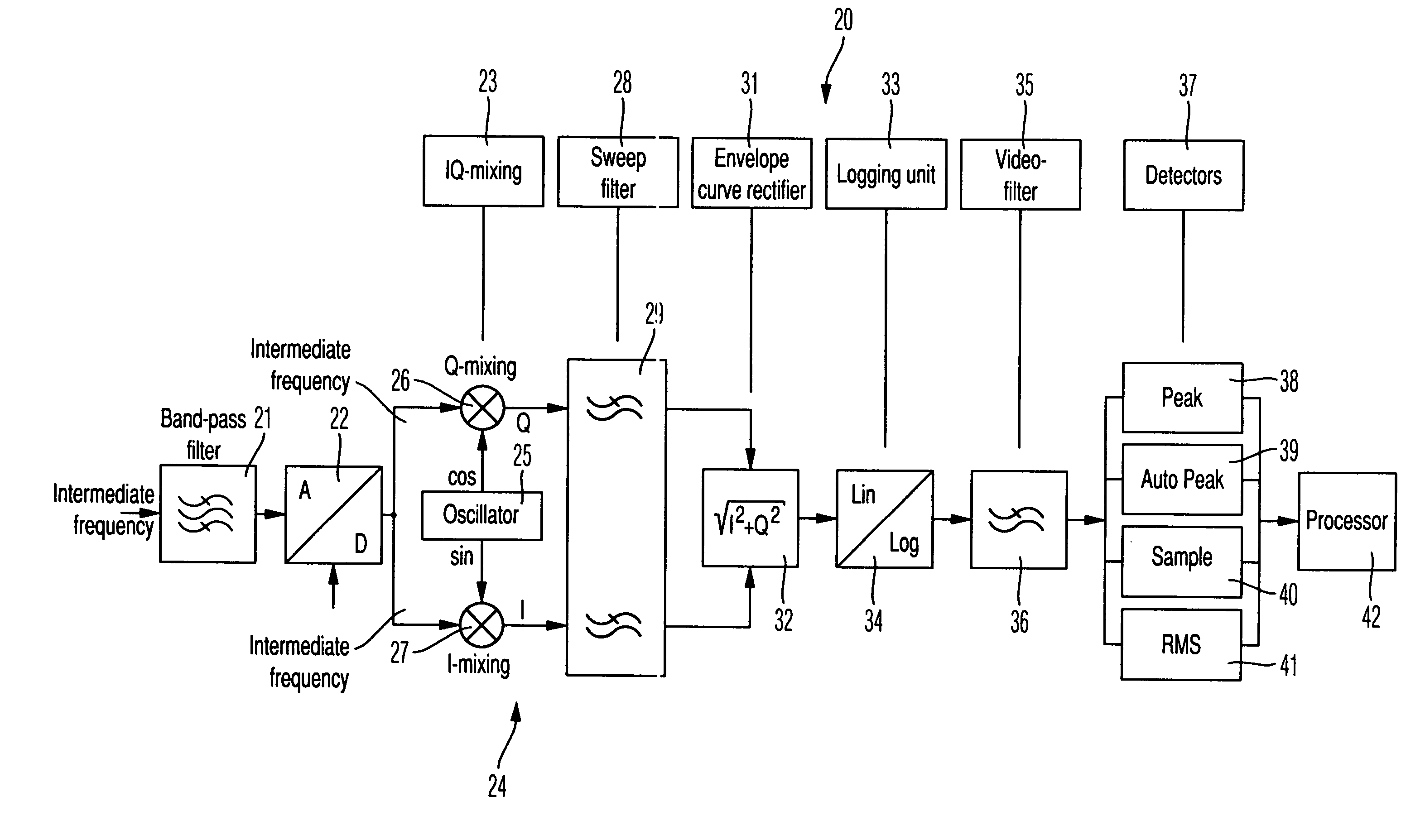
[0016]FIG. 1 provides an overview of a spectrum analyser 20, in which the resolution filter 29 according to the invention is used. FIG. 1 shows only the region of the signal below the intermediate frequency level, which is relevant here.

[0017] The intermediate frequency signal marked ZF in the drawings is filtered in a band-pass filter 21. The band-pass filter 21 is connected to an analog / digital converter 22. This is followed by the I / Q mixing 23 in an I / Q demodulator 24, which, in the conventional manner, comprises a local oscillator 25 with two outputs phase-displaced through 90°, which are supplied, together with the filtered and A / D-converted intermediate frequency signals, to a mixer 27 of the I-branch and a mixer 26 of the Q-branch respectively.

[0018] This stage is followed by a digital filtering 28 with the resolution filter 29 according to the invention. An envelope-curve rectification 31 then takes place in an envelope-curve rectifier 32. Logging 33 is implemented in a l...


PUM


Abstract

A spectrum analyzer is described which comprises a mixer for mixing the conjugate complex input signal v*(t) into a base band signal x(t), and a resolution filter for narrow-band filtering the base band signal. The resolution filter has a complex, discrete impulse response using a variation parameter k0 set to compensate for the frequency overshoot determined by the group delay of the resolution filter.

Description

FIELD OF THE INVENTION [0001] The invention relates to a resolution filter for a spectrum analyser. BACKGROUND OF THE INVENTION [0002] In spectrum analysis, a specified frequency range is “swept” with a resolution filter with a specified bandwidth. The resolution filter is therefore also sometimes referred to as a sweep filter. A resolution filter of this kind for a spectrum analyser with an analogous structure is known, for example, from U.S. Pat. No. 5,736,845. With resolution filters of the known, analogous structure, only a limited sweep rate can be achieved; the so-called K-factor, which indicates the rate of sweep, is limited in resolution filters of the known structure. [0003] It has been assumed hitherto in the context of spectrum analysis that it is possible to sweep within a Tres in the order of magnitude around 1 / Bres=Tres, so that the resolution filter can still build up. However, this statement is only correct if a fixed filter is assumed for all the sweep rates. [0004]...

Claims


Application Information

Patent Timeline
IPC IPC(8): G01R23/165G01R23/173H03H17/02
CPCH03H17/02G01R23/173
Inventor SCHMIDT, KURT
Owner ROHDE & SCHWARZ GMBH & CO KG
Why Eureka
Try Eureka