Device for Locating Metallic Objects and Methods for Adjusting Such a Device

a technology for locating metallic objects and detectors, applied in the direction of magnetic properties, instruments, material magnetic variables, etc., can solve the problems of narrow tolerances of components used, high cost, and small magnitude of the effect of objects to be located on the coil or the coil of the detector system

Inactive Publication Date: 2007-09-27
ROBERT BOSCH GMBH
View PDF8 Cites 7 Cited by
  • Summary
  • Abstract
  • Description
  • Claims
  • Application Information

AI Technical Summary

Problems solved by technology

A technical difficulty encountered in the detection of metallic objects is the fact that the magnitude of the effect of the objects to be located on the coil or coils of the detector system is very small.
A high offset of this type makes it difficult to detect very small inductive changes that are caused by a metallic object that enters the vicinity of the detector.
The need to detect a very small change in inductivity on a very large offset signal also requires that components be used that have narrow tolerances and are therefore expensive.
It also requires that extremely low-noise analogue electronics be used, which markedly increases the costs for a locating device of this type.
When assembly or manufacturing tolerances are not met, or when individual components drift relative to each other, the result measured by a device of this type is inevitably corrupted.
It has been shown that adequate compensation of the flux components cannot be realized in actual series production.
This time-consuming calibration process also has the potential for considerable error and damage if a user does not perform it properly.

Method used


Image

  • Device for Locating Metallic Objects and Methods for Adjusting Such a Device
  • Device for Locating Metallic Objects and Methods for Adjusting Such a Device
  • Device for Locating Metallic Objects and Methods for Adjusting Such a Device

Examples


Embodiment Construction

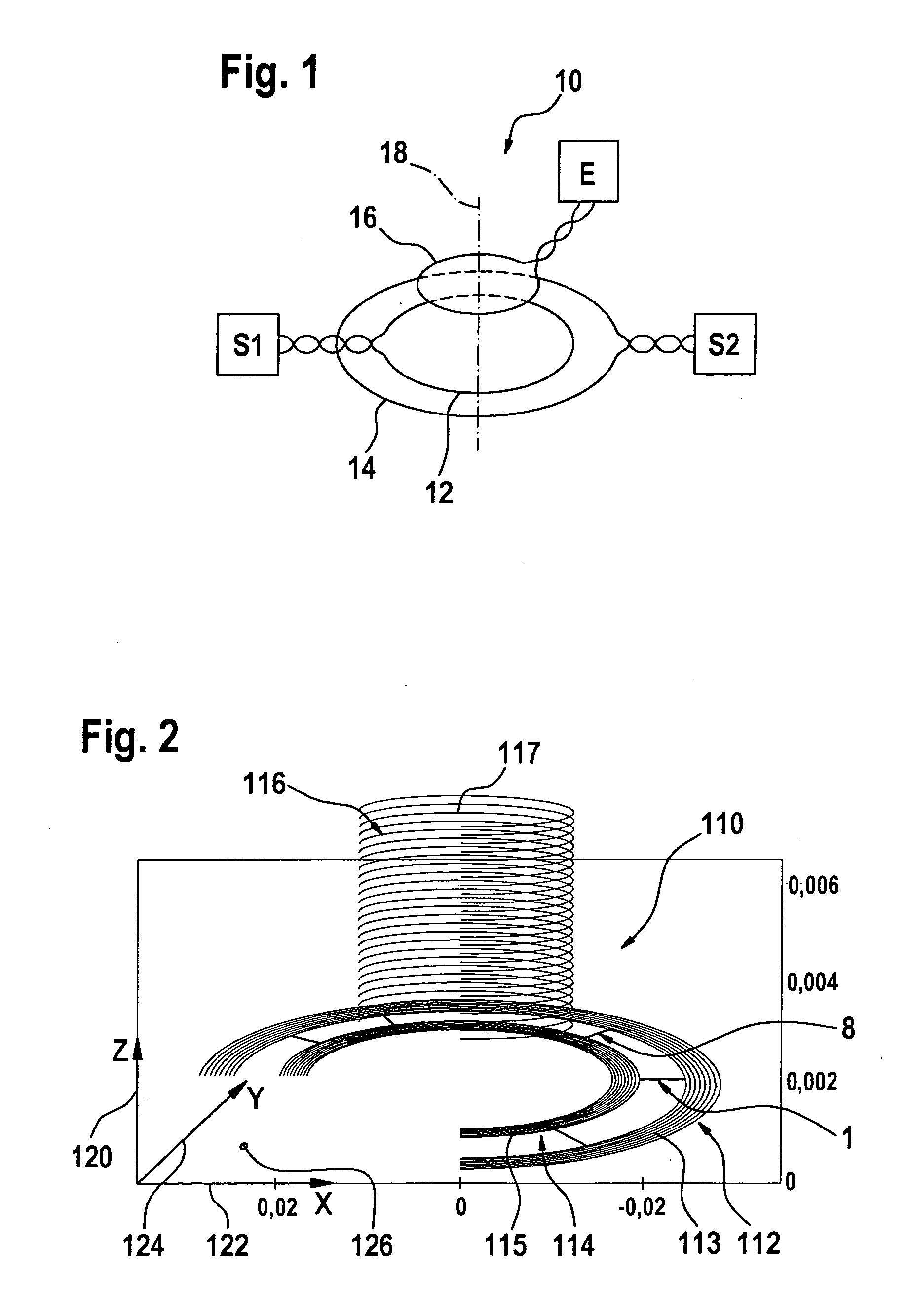
[0048]FIG. 1 shows the basic design of an inductive compensation sensor for locating metallic objects, according to the related art. A detector of this type includes three coils in its sensor geometry 10. A first transmit coil 12, which is connected to a first transmitter S1, a second transmit coil 14, which is connected to a second transmitter S2, and a receive coil 16, which is connected to a receiver E. Each coil is depicted as a circular line in this case. The arrangement of these three coils 12, 14, 16 is unique in that they are all located concentrically around a common axis 18. Individual coils 12, 14, 16 have different outer dimensions, so that coil 12 can be inserted in coil 14 coaxially to axis 18.

[0049] The two transmit coils 12 and 14 are supplied by their transmitters S1 and S2 with alternating currents with phase opposition. First transmit coil 12 therefore induces a flux in receive coil 16, which is oriented in the opposite direction from the flux induced by second t...


PUM


Abstract

The invention relates to a device for locating metallic objects, with at least one transmit coil (116) and at least one receive turn system (112, 114; 212, 214), which are inductively coupled to one another.
According to the invention, switching means (1, . . . , 8; 1′a, 2′a, 3′a, 1′b, 2′b, 3′b) are provided, which make it possible to vary the effective number of turns of the at least one receive turn system (112, 114; 212, 214).
The present invention also relates to a method for operating a device of this type, in particular a method with which the adjustment of a voltage U induced in a receive coil (112, 114; 212, 214) takes place by connecting an adjustment turn system (113, 115; 213′, 215′) to the turns (113, 115; 213, 215) of the receive turn system (112, 114; 212, 214).

Description

[0001] The present invention relates to a device for locating metallic objects according to the preamble of Claim 1, and a method for adjusting a device of this type. RELATED ART [0002] Currently, detectors for locating metallic objects hidden in construction materials typically operate using inductive methods. They are based on the fact that conductive and ferromagnetic materials influence the properties of an electromagnetic coil located nearby. The changes in the inductive properties caused by metallic objects are registered by a receiving circuit of a detector of this type. In this manner, metallic objects enclosed in a wall can be located using one or more coils guided over the wall. [0003] A technical difficulty encountered in the detection of metallic objects is the fact that the magnitude of the effect of the objects to be located on the coil or coils of the detector system is very small. This applies mainly with regard for the influence by non-ferromagnetic objects, e.g., c...

Claims


Application Information

Patent Timeline
Patent Type & Authority Applications(United States)
IPC IPC(8): G01R33/12
CPCG01V3/107
Inventor HAASE, BJOERN
Owner ROBERT BOSCH GMBH
Why Eureka
Try Eureka