
Delay control circuit

a control circuit and delay technology, applied in the direction of pulse automatic control, pulse manipulation, pulse technique, etc., can solve the problems of large circuit area, high power consumption in the case of analog circuit implementation, difficult to realize a configuration of small area and low power consumption simultaneously, and achieve low power consumption, small area, and maintain acceptable accuracy

Active Publication Date: 2007-09-27
MONTEREY RES LLC
View PDF10 Cites 3 Cited by
  • Summary
  • Abstract
  • Description
  • Claims
  • Application Information

AI Technical Summary

Benefits of technology

"The present invention provides a delay control circuit that can accurately control delay while being small and low-powered. The circuit includes two variable delay circuits that delay an input signal and generate corresponding delay signals. A control circuit generates a control signal to ensure the two delays are equal, and a generation circuit combines the two delay signals to generate a final delay signal. The technical effect of this invention is to provide a reliable and efficient delay control circuit for various applications."

Problems solved by technology

In the conventional techniques of the PLL and DLL, although a highly accurate control is realized, the circuit area is large and the power consumption is high in the case of implementation as an analog circuit.
When it is desired to introduce the arbitrary delay, especially a highly accurate and relatively large delay, into the clock signal in a conventional technique, it is difficult to realize a configuration of a small area and low power consumption simultaneously.

Method used


Image

  • Delay control circuit
  • Delay control circuit
  • Delay control circuit

Examples


Embodiment Construction

[0033]Hereinbelow, the most preferred embodiment for implementing the present invention is explained in detail, by referring to the drawings.

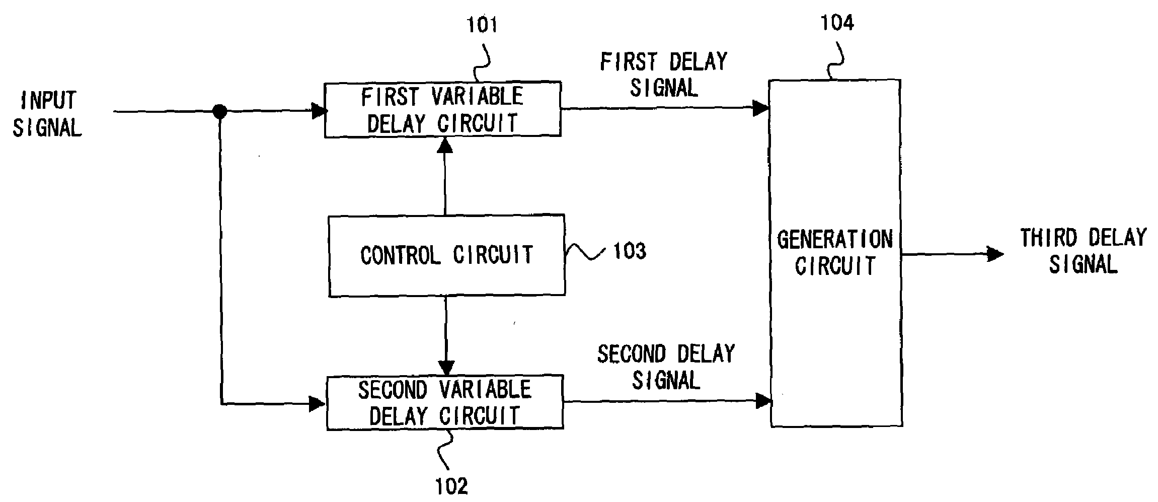
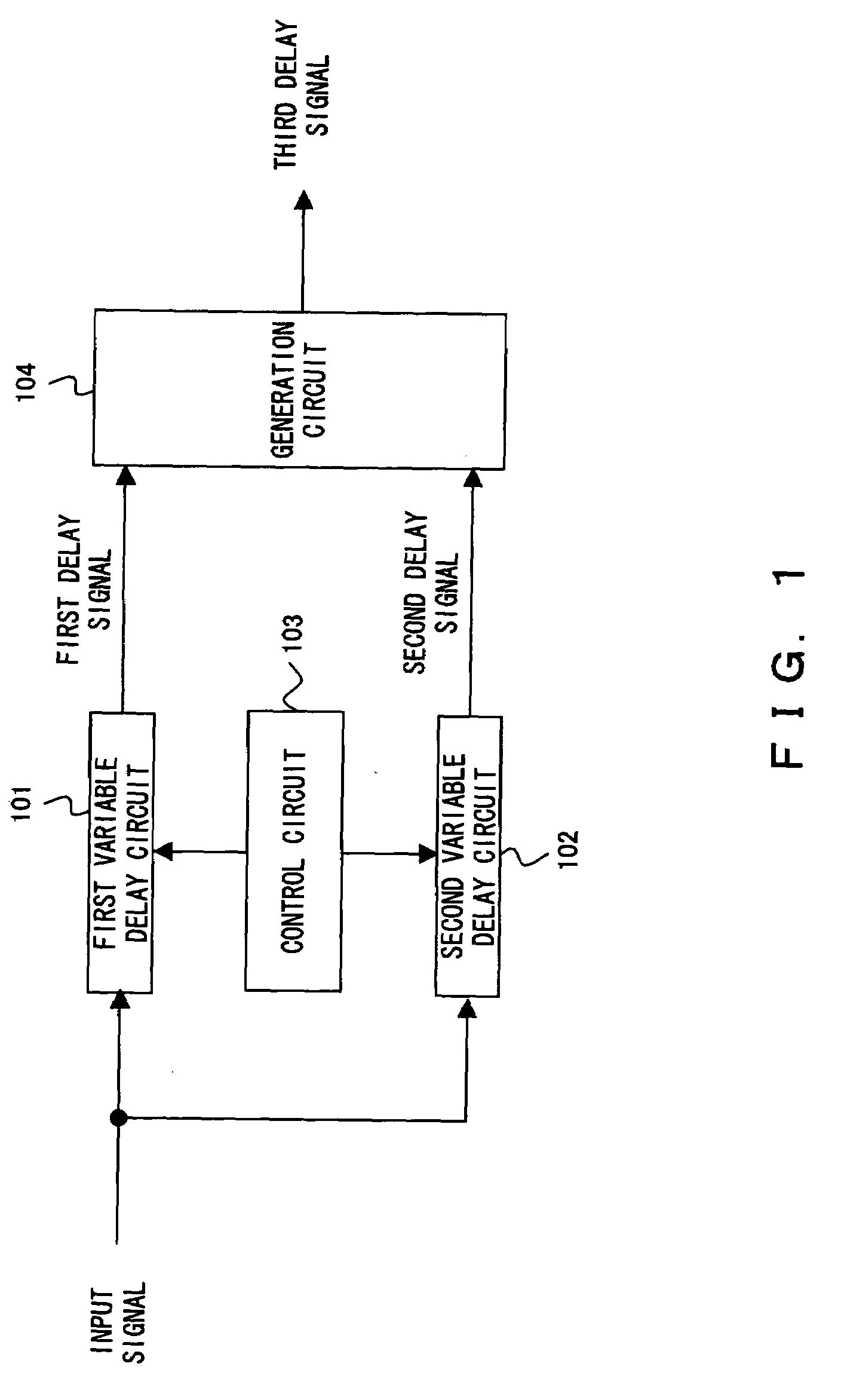
[0034]FIG. 1 is a principle view of a delay control circuit according to the present invention. The delay control circuit of FIG. 1 comprises a first variable delay circuit 101, a second variable delay circuit 102, a control circuit 103, and a generation circuit 104.

[0035]The first variable delay circuit 101 delays an input signal, introduces a first delay into a first edge which is one of rising and falling edges of the input signal, and generates a first delay signal. The second variable delay circuit 102 delays the above input signal, introduces a second delay into a second edge which is the other edge of the input signal, and generates a second delay signal.

[0036]The control circuit 103 generates a control signal for controlling the first variable delay circuit 101 and the second variable delay circuit 102 such that the first delay and the ...


PUM


Abstract

A first variable delay circuit delays an input signal, introduces a first delay into a first edge of the input signal, and generates a first delay signal. A second variable delay circuit delays the input signal, introduces a second delay into a second edge, and generates a second delay signal. A control circuit controls the first variable delay circuit and the second variable delay circuit such that the first delay and the second delay are identical. A generation circuit combines the first edge of the first delay signal and the second edge of the second delay signal, and generates a third delay signal.

Description

CROSS REFERENCE TO RELATED APPLICATIONS [0001]This application is based upon and claims the benefit of priority from the prior Japanese Patent Application No. 2006-081698, filed Mar. 23, 2006, the entire contents of which are incorporated herein by this reference.BACKGROUND OF THE INVENTION[0002]1. Field of the Invention[0003]The present invention relates to a delay control circuit for introducing an arbitrary delay into a signal.[0004]2. Description of the Related Art[0005]Generally, there are two ways below for introducing the arbitrary delay (or an arbitrary phase difference) into a clock signal or the like.[0006](1) PLL (Phase Locked Loop) or DLL (Delay Locked Loop)[0007](2) Buffer for desired delay[0008]The Patent Document 1 below discloses a variable delay circuit for controlling a delay time by changing a gate capacity of a transistor which is parallelly connected to a transmission path of a signal. The Patent Document 2 discloses a DLL circuit which is used for a memory devi...

Claims


Application Information

Patent Timeline
Patent Type & Authority Applications(United States)
IPC IPC(8): H03H11/26H03K5/131H03K5/135
CPCH03K2005/00065H03K2005/00071H03K5/133H03L7/0814H03L7/089H03L7/0805H03L7/0816H03L7/06H03K5/131
Inventor ARIYOSHI, KATSUHIKOSETSU, SOUYOUOBARA, RYUSUKE
Owner MONTEREY RES LLC
Learn More