Cleaning blade, method fabricating cleaning blade, and cleaning apparatus for liquid discharge head

a technology of cleaning blades and cleaning blades, which is applied in printing and other directions, can solve the problems of unstable deformation of the wiping member, difficulty in normal ink discharge, and difficulty in sufficiently wiping off thickened ink and waste such as paper dust attached to the ink discharge area, and achieves flatness of the tip end part of the wipe part, high accuracy, and uniform length. uniform

Inactive Publication Date: 2007-09-27
SONY CORP
View PDF4 Cites 35 Cited by
  • Summary
  • Abstract
  • Description
  • Claims
  • Application Information

AI Technical Summary

Benefits of technology

[0013]Accordingly, it is desirable to provide a long cleaning blade for a liquid discharge head, in which the flatness and the stiffness of its tip end part can be secured in the entire length, the mounting accuracy can be attained easily, and slits in narrow width can be formed easily, a method of fabricating a cleaning blade, and a cleaning apparatus for a liquid discharge head.
[0018]According to the cleaning blade, the method of fabricating the same, and the cleaning apparatus for a liquid discharge head according to an embodiment of the invention, since the supporting plate and the wipe part are formed in one piece, the cleaning blade has the stiffness in the entire length. Furthermore, the supporting plate and the elastic part configuring the wipe part are formed in one piece, and then the piece is cut in accordance with the shape of the wipe part. Therefore, the flatness of the tip end part of the wipe part can be secured highly accurately in the entire length. Since the wipe part is formed by cutting the elastic part after punched out, two corner parts of the wipe part in the sectional form can be formed square.
[0019]Therefore, since the flatness and the stiffness are provided highly accurately in the entire length of the wipe part, foreign substances attached to the liquid discharge area can be surely wiped off in the overall width of the liquid discharge area. Furthermore, since two corner parts of the wipe part in the sectional form have square edges, the performance of removing ink and waste is improved.
[0020]Moreover, in the method of fabricating a cleaning blade according to an embodiment of the invention, the supporting plate is formed in one piece with the wipe part, and then cuts are formed in the wipe part. More specifically, cuts are formed in the state in which internal stress works in the wipe part in the longitudinal direction due to the difference in the linear expansion coefficients between the supporting plate and the wipe part. Thus, stresses to contract inward work in each of the cut areas. Therefore, the slits in narrow width can be formed uniformly in the wipe part in the longitudinal direction. Furthermore, according to the cleaning blade with these slits and the cleaning apparatus for a liquid discharge head, in each of the wipe pieces separated by the slits, the cut areas are not closely contacted with each other, or the wipe pieces are not overlapped with each other due to stress, or the cleaning performance is not deteriorated.

Problems solved by technology

In this type of ink jet printer, when it does not continuously operate to print for a long time and ink is not discharged from the ink discharge nozzles of the print head, the ink attached near the ink discharge nozzle in the ink discharge area due to the previous print operation sometimes evaporates, dries, thickens and hardens, causing the difficulty in normal ink discharge.
More specifically, when the tip end area of the wiping member is not formed flat, even though the ink discharge area of the print head is rubbed, it is difficult to sufficiently wipe off thickened ink and waste such as paper dust attached to the ink discharge area.
Furthermore, when the stiffness of the wiping member is not retained in the entire length touched to the ink discharge area, the wiping member slides over the ink discharge area at a predetermined pressure, deformation generated in the wiping member is unstable, and the wiping performance is unstable depending on the places in the wiping member.
However, two corners in sectional form of the tip end of the wiping member to rub the ink discharge area are sometimes rounded, causing deteriorated cleaning performance of the ink discharge area in the width direction.
However, the stiffness of the wiping member is deteriorated when the wiping member is punched out, it tends to expand and contract in the plan direction.
Therefore, the accuracy of the distance between the mounting hole and the tip end part of the wiping member is sometimes deteriorated, and the flatness of the tip end part might not be secured.
However, as the slit width becomes narrower, more machining accuracy is demanded, and it is difficult to form the slits by punching out for the slit width in μm order.
Furthermore, when the slit in narrow width is formed only by cutting the tip end part of the wiping member with a cutter, the cut areas of the adjacent wiping members are closely contacted with each other, or the pieces of the wiping members separated by the slits are overlapped with each other in places when the wiping member rubs the ink discharge area, causing places not wiped or no capillary attraction working.
Moreover, the wiping member is mounted on the supporting plate to contract the wiping member because of the difference in the linear expansion coefficients thereof, and thus it is difficult to maintain the dimensional accuracy of the length and width of the slit in punching out.

Method used


Image

  • Cleaning blade, method fabricating cleaning blade, and cleaning apparatus for liquid discharge head
  • Cleaning blade, method fabricating cleaning blade, and cleaning apparatus for liquid discharge head
  • Cleaning blade, method fabricating cleaning blade, and cleaning apparatus for liquid discharge head

Examples


Embodiment Construction

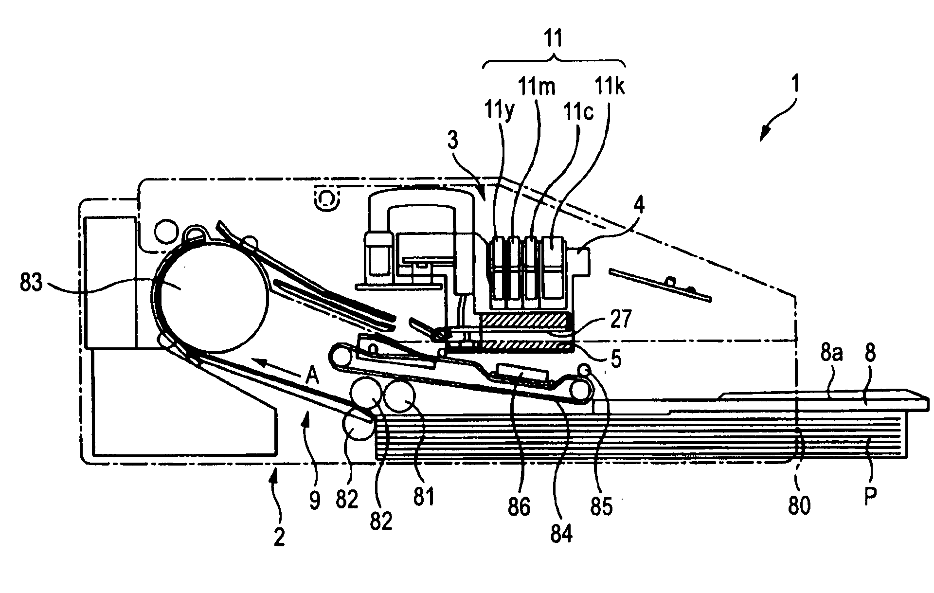
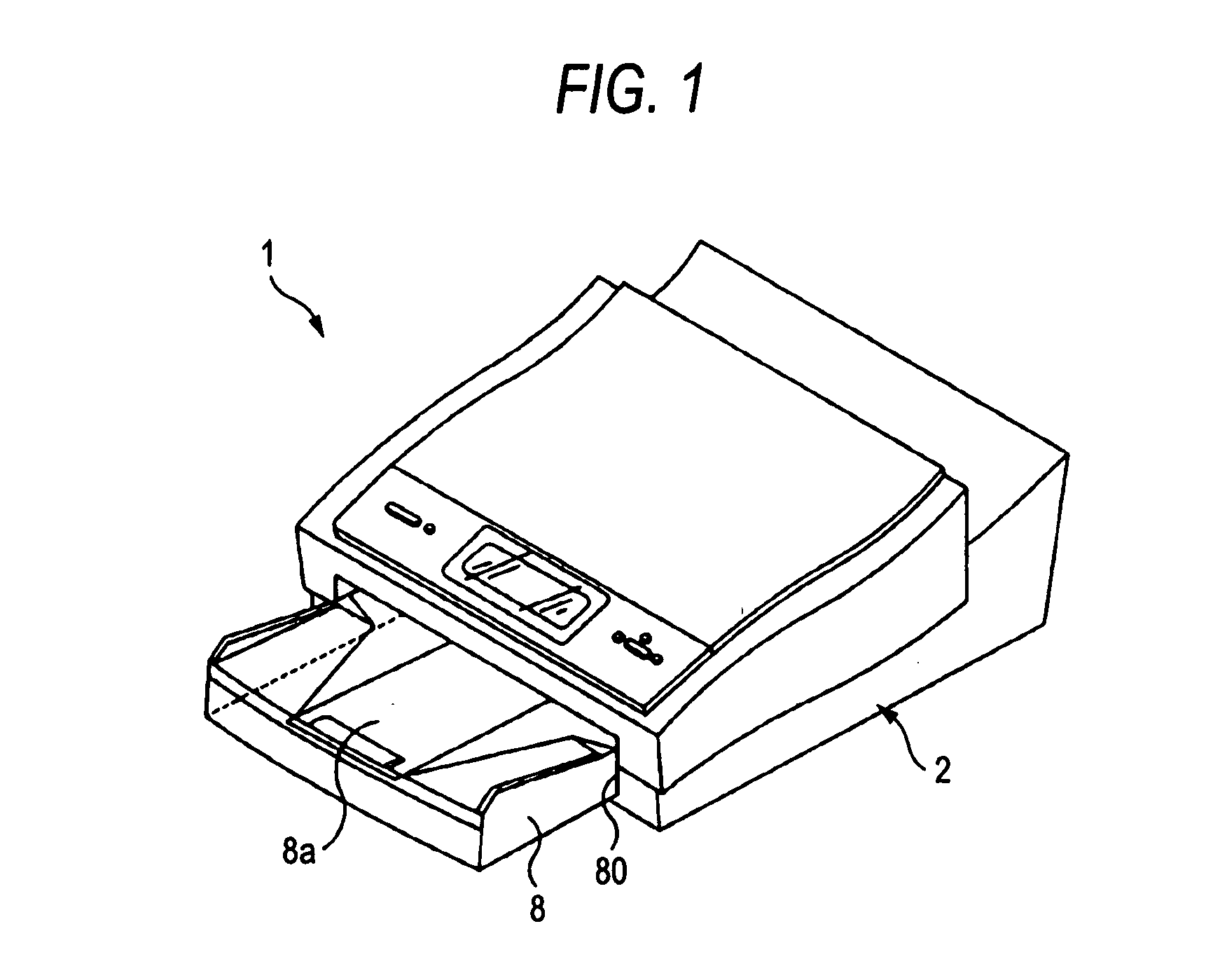
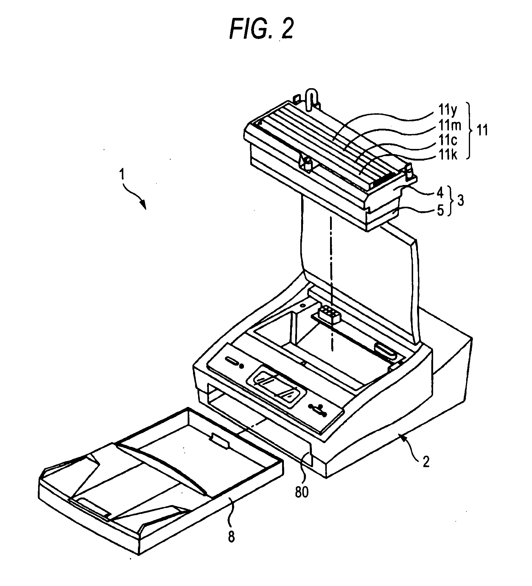
[0053]Hereinafter, a cleaning blade, a method of fabricating a cleaning blade, and a cleaning apparatus for a liquid discharge head according to an embodiment of the invention will be described in detail with reference to the drawings. The cleaning blade according to an embodiment of the invention is used for an ink discharge apparatus, a so-called ink jet printing apparatus (hereinafter, denoted as a printing apparatus) which discharges ink onto a paper sheet to be a target object and prints images and characters thereon. In addition, an ink jet printing apparatus 1 here is a so-called line scan head printing apparatus in which ink discharge nozzles are arranged as matched with the print span of a paper sheet.

[0054]As shown in FIGS. 1 and 2, the printing apparatus 1 has a printer main body 2. The printer main body 2 has an ink discharge head 3 including a head cartridge 4 which is mounted with ink cartridges to discharge ink and a headcap 5 which protects the head cartridge 4, a ca...


PUM


Abstract

A cleaning blade which wipes a liquid discharge area by being moved relatively with respect to the liquid discharge area of a liquid discharge head having the liquid discharge area in which liquid discharge nozzles are arranged to discharge a liquid is disclosed. The cleaning blade includes: a supporting plate which has an adhesive agent layer on its front surface; and a wipe part which is slid and contacted with the liquid discharge area, the wipe part formed in which an elastic part formed of a synthetic resin is formed in one piece on the adhesive agent layer, and a tip end thereof is cut in a predetermined shape.

Description

CROSS REFERENCES TO RELATED APPLICATIONS[0001]The present invention contains subject matter related to Japanese Patent Application JP 2006-085986 filed in the Japanese Patent Office on Mar. 27, 2006, the entire contents of which being incorporated herein by reference.BACKGROUND OF THE INVENTION[0002]1. Field of the Invention[0003]The present invention relates to a liquid discharge apparatus which discharges a liquid onto a target object from a liquid discharge nozzle formed on a liquid discharge head, particularly to a cleaning blade which cleans a liquid discharge head.[0004]2. Description of the Related Art[0005]An image forming apparatus in an ink jet printing system such as an ink jet printer is widely available in that its running costs are inexpensive and it is easy to print color images and to reduce the apparatus size. The ink jet printer is configured in which a very small quantity of ink is discharged from fine ink discharge nozzles arranged in an ink discharge area of a p...

Claims


Application Information

Patent Timeline
Patent Type & Authority Applications(United States)
IPC IPC(8): B41J2/165
CPCB41J2/16535B41J2/01B41J2/165
Inventor NISHI, SHOTAFUJIKI, SHIGEYOSHIMATSUDA, MANABUYAKURA, YUJIANDO, MAKOTO
Owner SONY CORP
Why Eureka
Try Eureka