Total wrist prosthesis

a wrist and prosthesis technology, applied in the field of total wrist prosthesis, can solve the problems of missing the provision for additional small hand rotational movements and disjointness, and achieve the effect of preventing the separation of the carpal componen

Inactive Publication Date: 2007-09-27
ASCENSION ORTHOPEDICS
View PDF21 Cites 74 Cited by
  • Summary
  • Abstract
  • Description
  • Claims
  • Application Information

AI Technical Summary

Benefits of technology

[0004] The invention seeks to provide a prosthesis which allows hand movements in three planes and which provides a reliable joint, reducing the chances of dislocation and / or loosening.
[0008] c) an intermediate bearing component that is connected to the carpal component so as to allow rotational movement of the carpal component relative to the intermediate bearing component and thereby allow small rotational movement of the hand relative to the arm, and that articulates with a facing surface of the radial component so as to allow only hinged movement between the intermediate bearing component and the radial component in two transverse planes so as to allow for flexion and extension movement of the hand in a first plane and ulnar and radial deviation in a second transverse plane.
[0011] In one embodiment the radial body has a toroidal or ellipsoidal concave recess which engages and articulates with a toroidal or ellipsoidal convex surface on the intermediate bearing component. The carpal body may have a projection on its side remote from its stem which is rotatively received in a recess in the intermediate bearing component. In one embodiment, the projection is generally cylindrical, having a pair of opposed lugs extending from the cylindrical wall thereof, the projections are received and axially constrained in an annular groove in the recess of the intermediate bearing component to prevent separation of the carpal component from the intermediate bearing component. The projecting lugs may slide through diametrically opposed keyways in the intermediate bearing component to reach the groove; rotation then assembles the intermediate bearing component with carpal component.

Problems solved by technology

However, provision is missing for additional small rotational movements of the hand relative to the arm in a third plane.
Also some prosthesis parts may be joined too loosely and may lead to disjointing problems.

Method used


Image

  • Total wrist prosthesis
  • Total wrist prosthesis
  • Total wrist prosthesis

Examples


Embodiment Construction

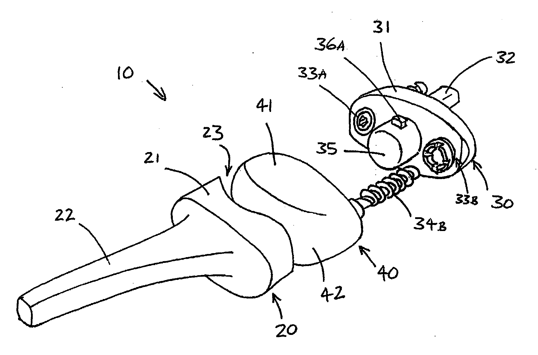
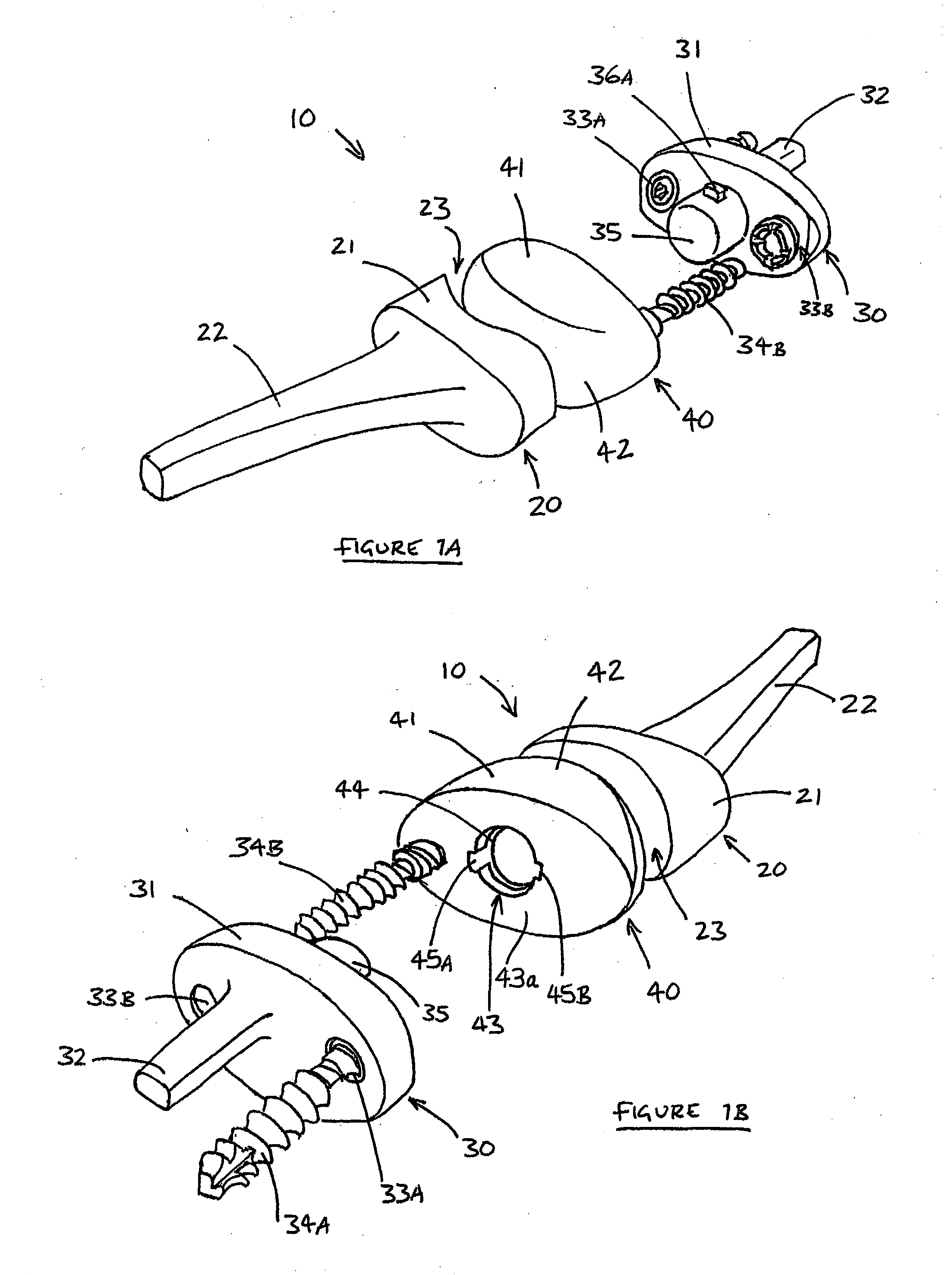
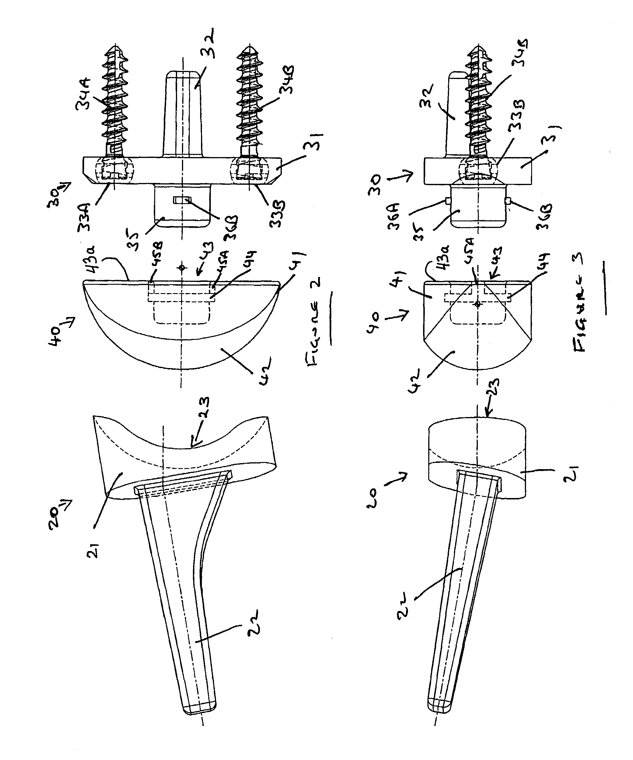
[0019] FIGS. 1 to 3 show a prosthesis 10 which comprises a proximal radial component 20, a distal carpal component 30, and an intermediate bearing component 40.

[0020] Proximal radial component 20 may be formed from any suitable material such as a cobalt chrome alloy. Radial component 20 has a generally oval body 21 and a stem 22 extending from one side of the body that allows fixation into the resected distal end of the radius. Part of the body and / or shaft may be coated with a textured bone ingrowth surface to provide for more secure joinder to the bone.

[0021] Radial body 21 has a toroidal or ellipsoidal concave surface 23 on its side remote from its stem 22. This double-curved surface 23 has its larger radius of curvature in the direction of body length and its smaller radius of curvature in the direction of body width, normal to the larger radius of curvature. Also as clear from the dotted lines in FIGS. 2 and 3, one side and one end wall of the body 21 may be higher than its o...


PUM


Abstract

Total wrist prosthesis comprising a radial component with a stem for fixation into the radius, a carpal component with one or more stems for fixation into the capitate and an intermediate bearing component which articulates with the radial component and allows rotational movement of the carpal component relative to the radial component plus hinged movement in two transverse planes. The radial component body may have a concave or convex surface to articulate with a matching surface on the intermediate bearing component. The carpal body may have a projection which is received in a recess in a base surface of the intermediate bearing component, and which has a pair of lugs that are received in an annular groove in the recess for an axially secure connection that allows small relative rotational movement as permitted by tendons and ligaments of the wrist.

Description

[0001] This application is a divisional of U.S. application Ser. No. 10 / 746,982 filed Dec. 23, 2003, the disclosure of which is incorporated herein by reference.TECHNICAL FIELD OF THE INVENTION [0002] The present invention relates to a total wrist prosthesis. BACKGROUND OF THE INVENTION [0003] Various wrist prostheses have hitherto been known. Many of these allow for movement in two planes, namely flexion and extension movement in a first plane, and ulnar deviation and radial deviation in another plane. However, provision is missing for additional small rotational movements of the hand relative to the arm in a third plane. Also some prosthesis parts may be joined too loosely and may lead to disjointing problems. SUMMARY OF THE INVENTION [0004] The invention seeks to provide a prosthesis which allows hand movements in three planes and which provides a reliable joint, reducing the chances of dislocation and / or loosening. [0005] According to a particular embodiment of the present inven...

Claims


Application Information

Patent Timeline
Patent Type & Authority Applications(United States)
IPC IPC(8): A61F2/42
CPCA61B17/8047A61B17/86A61F2/4261A61F2002/30331A61F2002/30426A61F2310/00029A61F2002/3065A61F2002/4264A61F2002/4274A61F2220/0025A61F2220/0033A61F2002/30507
Inventor THOMAS, GARETHSTANLEY, JOHN KNOWLES
Owner ASCENSION ORTHOPEDICS
Why Eureka
Try Eureka