Method and an apparatus for measuring noise

a technology of signal noise and measurement apparatus, applied in the direction of noise figure or signal-to-noise ratio measurement, instruments, pulse characteristics measurement, etc., can solve the problem of limiting the accuracy of phase noise measurement, and limiting the improvement of the performance of the phase noise measurement apparatus. problem, to achieve the effect of reducing the spurious effect of this signal source, increasing the number of times processing is performed per unit of time, and reducing the spurious

Inactive Publication Date: 2007-09-27
AGILENT TECH INC
View PDF11 Cites 21 Cited by
  • Summary
  • Abstract
  • Description
  • Claims
  • Application Information

AI Technical Summary

Benefits of technology

[0015] By means of the present disclosure, phase noise is measured by correlating or cross spectrum processing; therefore, it is possible to measure phase noise of a lower level than in the past.
[0017] By means of the present disclosure, the above-mentioned correlating or cross spectrum processing is performed in a plurality of processing blocks; therefore, the number of times processing is performed per unit of time can be increased for each processing block and it is possible to measure noise of a lower level than when correlating or cross spectrum processing is performed a single time.
[0018] By means of the present disclosure, when noise is measured using correlating or cross spectrum processing, the frequency of the reference signal source is different from the other signal sources that participate in the measurements; therefore, it is possible to reduce the spurious effect of this signal source on the noise measured values.
[0019] By means of the present disclosure, when noise is measured using correlating or cross spectrum processing, the signals under test are distributed and each of the distributed signals under test is processed by a different signal processor; therefore, the effect of this signal processor on the noise measured value can be reduced. The effect of the present disclosure is obvious when, for instance, the signal processor is a frequency conversion means having a signal source.

Problems solved by technology

There are phase noise sources inside conventional apparatuses for measuring phase noise and there are limits to the phase noise measurement precision thereof.
However, there are several problems with the above-mentioned apparatus for measuring phase noise.
First, the necessary phase noise properties cannot be realized with conventional apparatuses for measuring phase noise.
However, when an apparatus for measuring phase noise is constructed using parts with a low phase noise property, noise is still generated from these parts; therefore, there are limits to the improvement in the performance of the apparatus for measuring phase noise.
Even if the measurement results are corrected using pre-determined phase noise components, it is not possible to completely eliminate the phase noise component generated inside the apparatus for measuring phase noise.
Moreover, when a conventional apparatus for measuring phase noise processes signals under test several times before phase noise is measured, the effect of the phase noise generated by this signal processing on the measurement results cannot be eliminated.
It is often difficult to pre-determine the phase noise generated by these additional apparatuses and circuits.
These measures raise total production cost and run contrary to the desired reduction in product cost.
Moreover, today there is a demand for such low phase noise properties that they cannot be attained even when the above-mentioned measures are implemented, and in such cases, even if production cost is raised, there is not a corresponding improvement in the required properties.

Method used


Image

  • Method and an apparatus for measuring noise
  • Method and an apparatus for measuring noise
  • Method and an apparatus for measuring noise

Examples


first embodiment

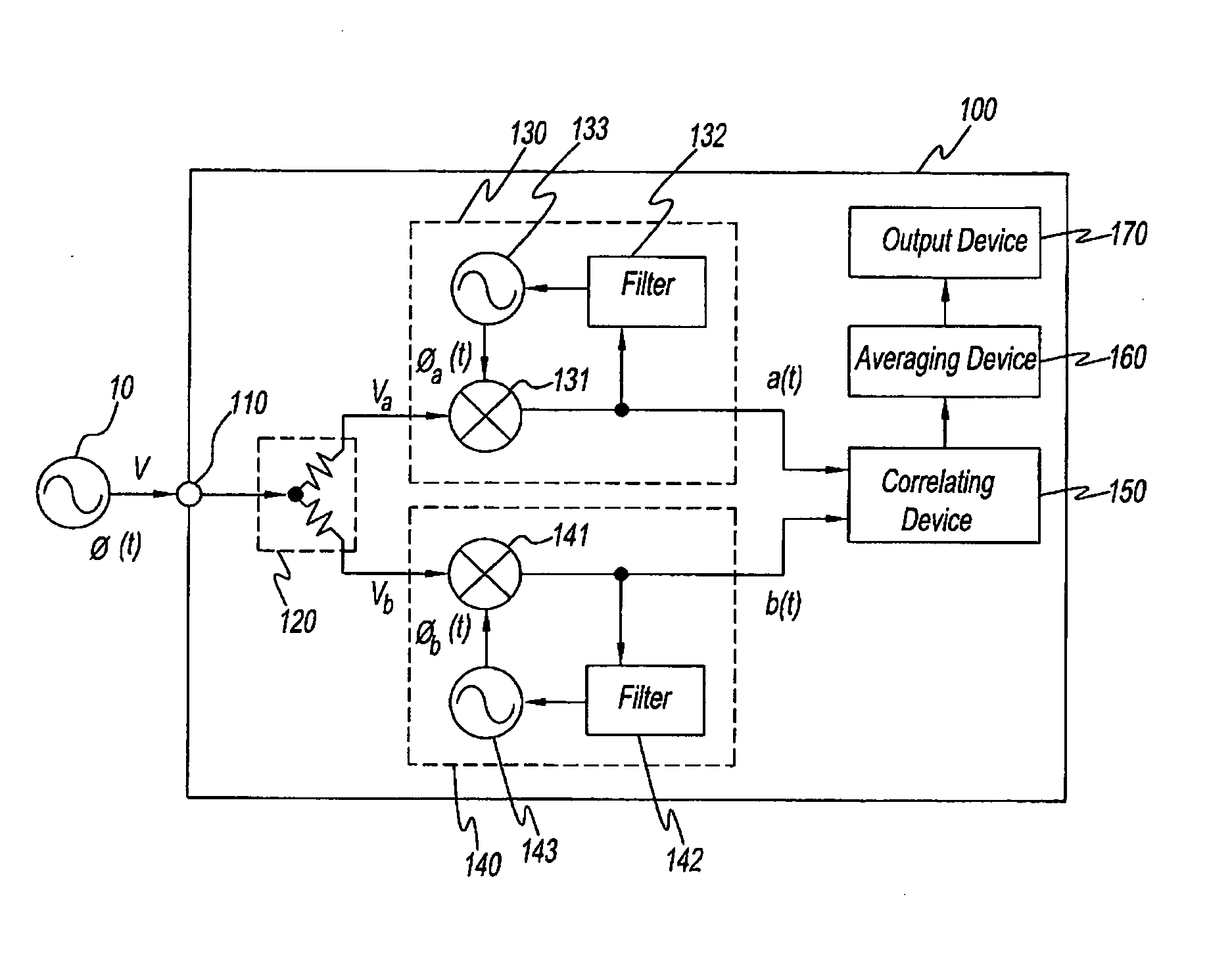
[0032] Preferred embodiments of the present disclosure will now be described while referring to the attached drawings as needed. the present disclosure is an apparatus 100 for measuring phase noise. A block diagram showing the structure of apparatus 100 for measuring phase noise is shown in FIG. 1. A device under test 10 and apparatus 100 for measuring phase noise are shown in FIG. 1.

[0033] Device under test 10 outputs signals V under test, which are the object of phase noise measurement. Device under test 10 is a signal source or a part, apparatus, or system that applies signals.

[0034] Phase noise measurement apparatus 100 is constructed as described below. That is, phase noise measurement apparatus 100 consists of an input terminal 110, a distributor 120, a PLL block 130, which is an example of a phase detection means, a PLL block 140, which is an example of a phase detection means, a correlating device 150; an averaging device 160, and an output device 170. Input terminal 110 is...

seventh embodiment

[0092] A block diagram showing the structure of the present disclosure, an apparatus 700 for measuring phase noise, is shown in FIG. 9. The same reference symbols are used in FIG. 9 for the same structural elements as in FIG. 1 and a description thereof is omitted. Apparatus 700 for measuring phase noise in FIG. 9 is apparatus 100 for measuring phase noise wherein a PLL block 710 is substituted for PLL block 130 and a PLL block 730 is substituted for PLL block 140. PLL block 710 is PLL block 130 in which a signal source 720 is substituted for signal source 133. PLL block 730 is PLL block 140 in which a signal source 740 has been substituted for signal source 143.

[0093] Signal source 720 has a reference signal source 721 and a synthesizer 722. Synthesizer 722 generates and outputs local signals while referring to the output signals of reference signal source 721. The frequency and phase of the output signals of synthesizer 722 are controlled by the output signals of filter 132. Moreo...

eighth embodiment

[0128] By means of the eighth embodiment, the cross spectrum of two phase signals is found for a plurality of frequency ranges having different frequency bands. That is, correlating blocks 920, 930, and 940 having different frequency bands essentially are assigned a frequency band and find the cross spectrum. As a result, it is not necessary for each correlating block to have excess operating functions. For instance, the total amount of memory inside each correlating block is much smaller than the amount of memory needed when a frequency band is not assigned. Moreover, when a plurality of cross spectra are obtained within the predetermined same time, correlating blocks 920, 930, and 940 perform vector averaging in terms of time on the respective resulting plurality of cross spectra. As a result, measurement resources are conserved and precision efficiency is improved in that noise flow is reduced.

[0129] The following modifications can be applied to each of the embodiments described ...


PUM


Abstract

A method for measuring noise of signals under test by frequency converting the signals under test to generate a first intermediate signals, frequency converting the signals under test to generate a second intermediate signals having frequency different from that of the first intermediate signals, and measuring the noise of signals under test from the first and the second intermediate signals using cross correlation processing or cross spectrum processing. The apparatus measures the phase noise of signals under test using this method.

Description

CROSS-REFERENCED APPLICATIONS [0001] This application is a Continuation-in-Part of U.S. patent application Ser. No. 11 / 102263, filed on Apr. 8, 2005.FIELD OF THE INVENTION [0002] The present disclosure pertains to an apparatus and a method for measuring the noise of signals and in particular, relates to a method and an apparatus for measuring noise which use cross correlation or cross spectrum. DISCUSSION OF THE BACKGROUND ART [0003] There are phase noise sources inside conventional apparatuses for measuring phase noise and there are limits to the phase noise measurement precision thereof. Conventional apparatuses for measuring phase noise are constructed from parts having low phase noise properties in order to alleviate the effects of this internal phase noise on the measurement results. Moreover, the phase noise generated inside the apparatus for measuring phase noise is pre-determined as an error component and the measurement results are corrected using this error component (for ...

Claims


Application Information

Patent Timeline
Patent Type & Authority Applications(United States)
IPC IPC(8): G06F19/00G01R25/00G01R23/16G01R29/02G01R29/26
CPCG01R25/00H04B3/462G01R29/26
Inventor BESSHO, MASAKIUGAWA, HIROAKIIWAI, JUNICHIMURATA, KOJI
Owner AGILENT TECH INC
Why Eureka
Try Eureka