Small DC motor
a dc motor and small technology, applied in the direction of electrostatic generator/motor, dynamo-electric machines, supports/enclosements/casings, etc., can solve the problems of ineffective torque generation of the armature core, shape relationship limit, etc., to reduce the quantity of expensive field magnets, increase the winding space, and reduce the effect of torqu
- Summary
- Abstract
- Description
- Claims
- Application Information
AI Technical Summary
Benefits of technology
Problems solved by technology
Method used
Image
Examples
embodiment 1
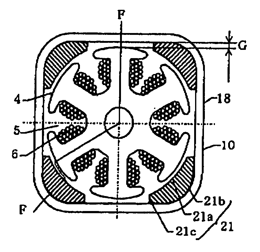
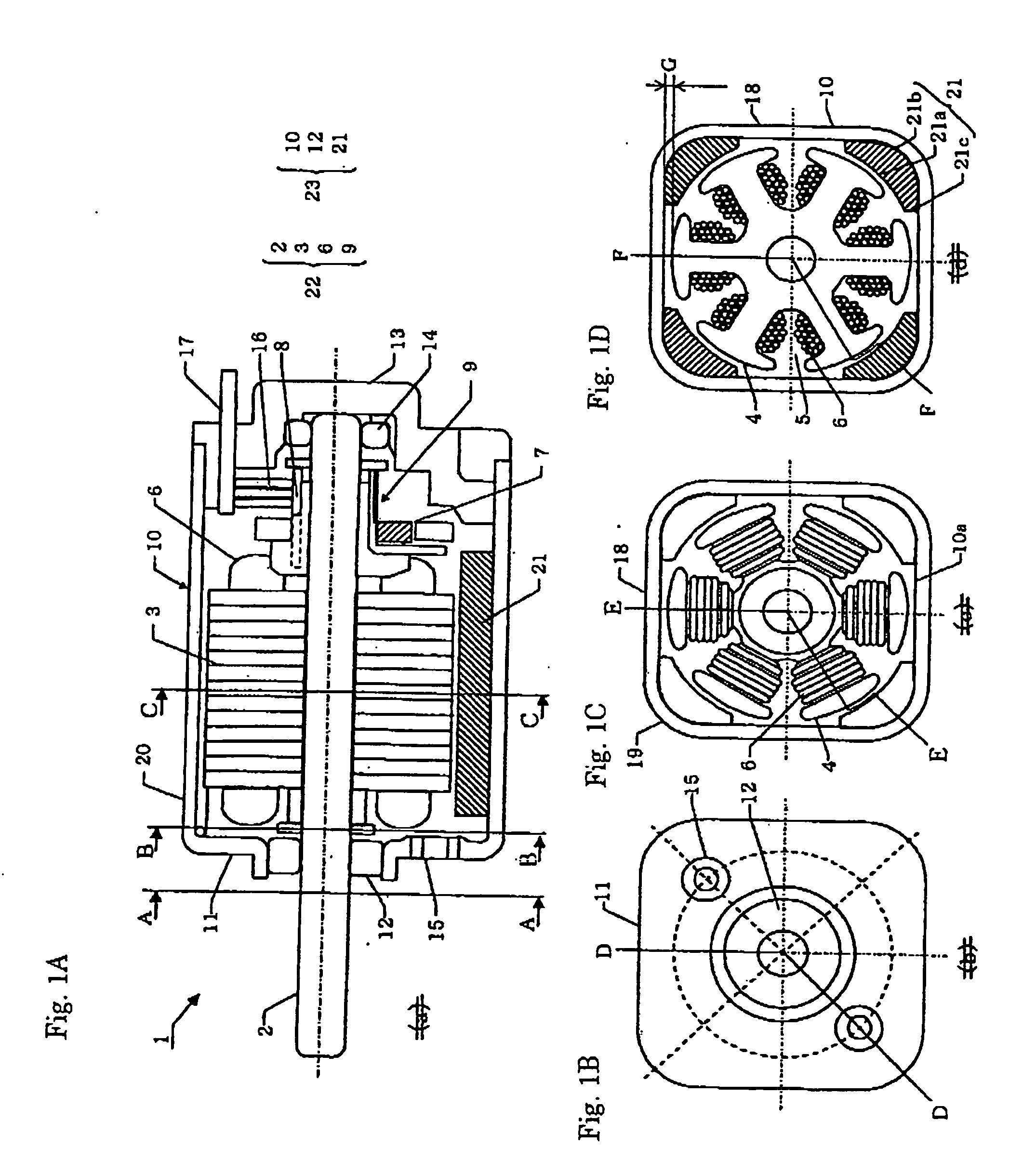
[0044]FIGS. 1A to 1D are drawings which illustrate the configuration of a small DC motor according to Embodiment 1 of the invention. In Embodiment 1, a case will be described in which an armature assembly has an armature core.
[0045]FIG. 1A is a sectional view taken along a longitudinal direction of a shaft, and in FIG. 1A, a segment from line A-A to line B-B is a sectional view taken along line D-D in FIG. 1B, a segment from line B-B to line C-C is a sectional view taken along line E-E in FIG. 1C, and a segment from line C-C to an end block is a sectional view taken along line F-F in FIG. 1D. FIG. 1B is a sectional view taken along line A-A in FIG. 1A, FIG. 1C is a sectional view taken along line B-B in FIG. 1A, and FIG. 1D is a sectional view taken along line C-C in FIG. 1A.
[0046] A small DC motor 1 illustrated in FIG. 1A has an armature assembly 22 and a frame assembly 23.
[0047] The armature assembly 22 has a shaft 2, an armature core 3 provided on the shaft 2, armature winding...
embodiment 2
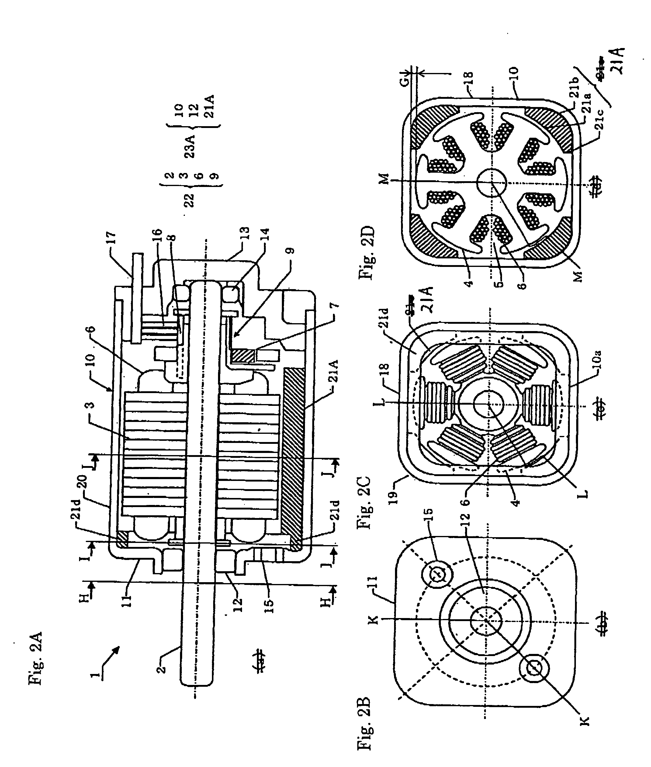
[0066]FIGS. 2A to 2D are drawings which illustrate the configuration of a small DC motor according to another embodiment of the invention.
[0067]FIG. 2A is a sectional view taken along a longitudinal direction of a shaft, and in FIG. 2A, a segment from line H-H to line I-I is a sectional view taken along line K-K in FIG. 2B, a segment from line I-I to line J-J is a sectional view taken along line L-L in FIG. 2C, and a segment from line J-J to an end block is a sectional view taken along line M-M in FIG. 2D.
[0068]FIG. 2B is a sectional view taken along line H-H in FIG. 2A, FIG. 2C is a sectional view taken along line I-I in FIG. 2A, and FIG. 2D is a sectional view taken along line J-J in FIG. 2A.
[0069]FIG. 2 has the same constituent elements except for field magnets as those of FIG. 1. Like reference numerals are given to like constituent elements, and the description thereof will be omitted.
[0070] A small DC motor 1 illustrated in FIG. 2A has an armature assembly 22 and a frame a...
embodiment 3
[0075]FIGS. 3A and 3B are drawings which illustrate the configuration of a small DC motor 1 according to a further embodiment of the invention. In addition, armature windings are omitted from the drawing. FIG. 3A is a sectional view which illustrates a cross section of a motor frame having a plurality of curved surfaces for 4 poles and 6 slots, FIG. 3B is a sectional view which illustrates a cross section of an octagonal motor frame for 8 poles and 12 slots, and FIG. 3C is a sectional view which illustrates a cross section of a square motor frame for 4 poles and 6 slots.
(Shapes of Motor Frame)
[0076] The motor frames of the aforesaid embodiments take the quadrangular shape as the basic shape thereof and are formed into the shape in which in the cross section of the motor frame resulting when the corner portions are collapsed inwardly while part of each of the sides of the quadrangular shape is left intact, the adjacent but spaced-apart sides of the motor frame are connected by the...
PUM
 Abstract
Description
Claims
Application Information
 - R&D
- Intellectual Property
- Life Sciences
- Materials
- Tech Scout
- Unparalleled Data Quality
- Higher Quality Content
- 60% Fewer Hallucinations
Browse by: Latest US Patents, China's latest patents, Technical Efficacy Thesaurus, Application Domain, Technology Topic, Popular Technical Reports.
© 2025 PatSnap. All rights reserved.Legal|Privacy policy|Modern Slavery Act Transparency Statement|Sitemap|About US| Contact US: help@patsnap.com


