Vacuum sewer system

a vacuum sewer and discharge valve technology, applied in sewer systems, lavatory sanitory, flushing devices, etc., can solve the problems of a rather complex solution and a distinctively high noise level of vacuum governed discharge valves

Active Publication Date: 2007-10-04
EVAC INT
View PDF4 Cites 20 Cited by
  • Summary
  • Abstract
  • Description
  • Claims
  • Application Information

AI Technical Summary

Benefits of technology

[0008]An object of the present invention is to achieve a vacuum sewer system in which the noise level during a discharge or flushing sequence is lowered. A further object of the present invention is to provide a discharge valve, which improves the operation of the vacuum sewer system. These objects are attained by a vacuum sewer system according to claim 1 and a discharge valve according to claim 11.
[0009]The basic idea of the invention is to provide the vacuum sewer system with an aeration means, a so-called rapid vent valve that provides for an effective and rapid closing of the discharge valve after discharge of the sewage from the sewage receptacle, which also results in a lower noise level. The effective and rapid closing of the discharge valve is achieved by a direct supply of supplementary air to the discharge valve. To this effect the vacuum sewer system comprises an aeration means, which is arranged to provide a direct fluid communication to the discharge valve. The control mechanism, which controls the discharge valve, is also arranged to control the function of the aeration means. Particularly, the discharge valve is provided with such an aeration means.
[0010]The aeration means is arranged to supply air to the discharge valve for rapidly closing the discharge valve after a discharge or flushing sequence. The aeration means is arranged to be closed when the discharge valve is provided with vacuum for opening the same for the discharge or flushing sequence. In this way, the aeration means affects the closure time, but does not interfere with the opening of the discharge valve.
[0015]The above provides easy and reliable ways to govern the function of the aeration means based on the vacuum control of the discharge valve provided by the control mechanism.

Problems solved by technology

Previously known vacuum governed discharge valves have a distinctively high noise level as the air-flow through the discharge valve is strongly choked or throttled when the discharge valve is closed.
These solutions are rather complex and provide a very limited result.

Method used


Image

  • Vacuum sewer system
  • Vacuum sewer system
  • Vacuum sewer system

Examples


first embodiment

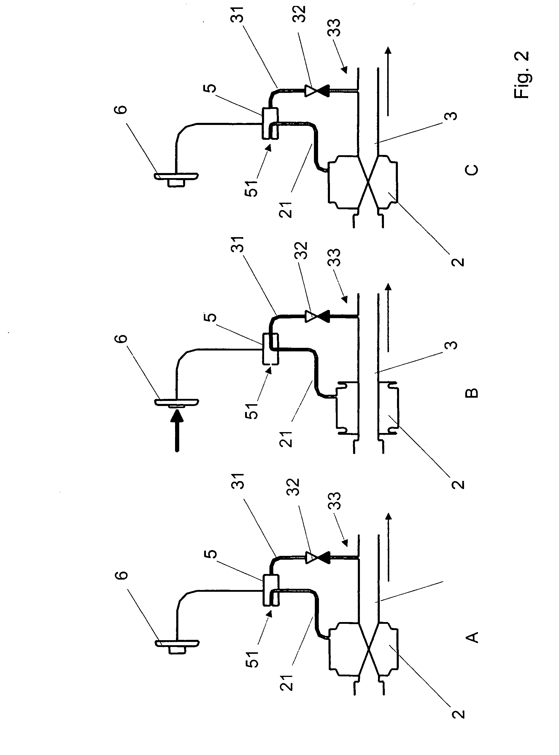
[0020]FIG. 3 illustrates a discharge or flushing sequence deploying the present invention,

second embodiment

[0021]FIG. 4 illustrates a discharge or flushing sequence deploying the present invention, and

third embodiment

[0022]FIG. 5 illustrates a discharge or flushing sequence deploying the present invention.

DETAILED DESCRIPTION OF THE DRAWINGS

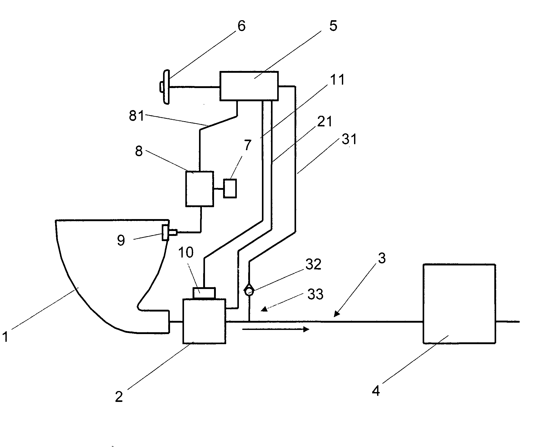
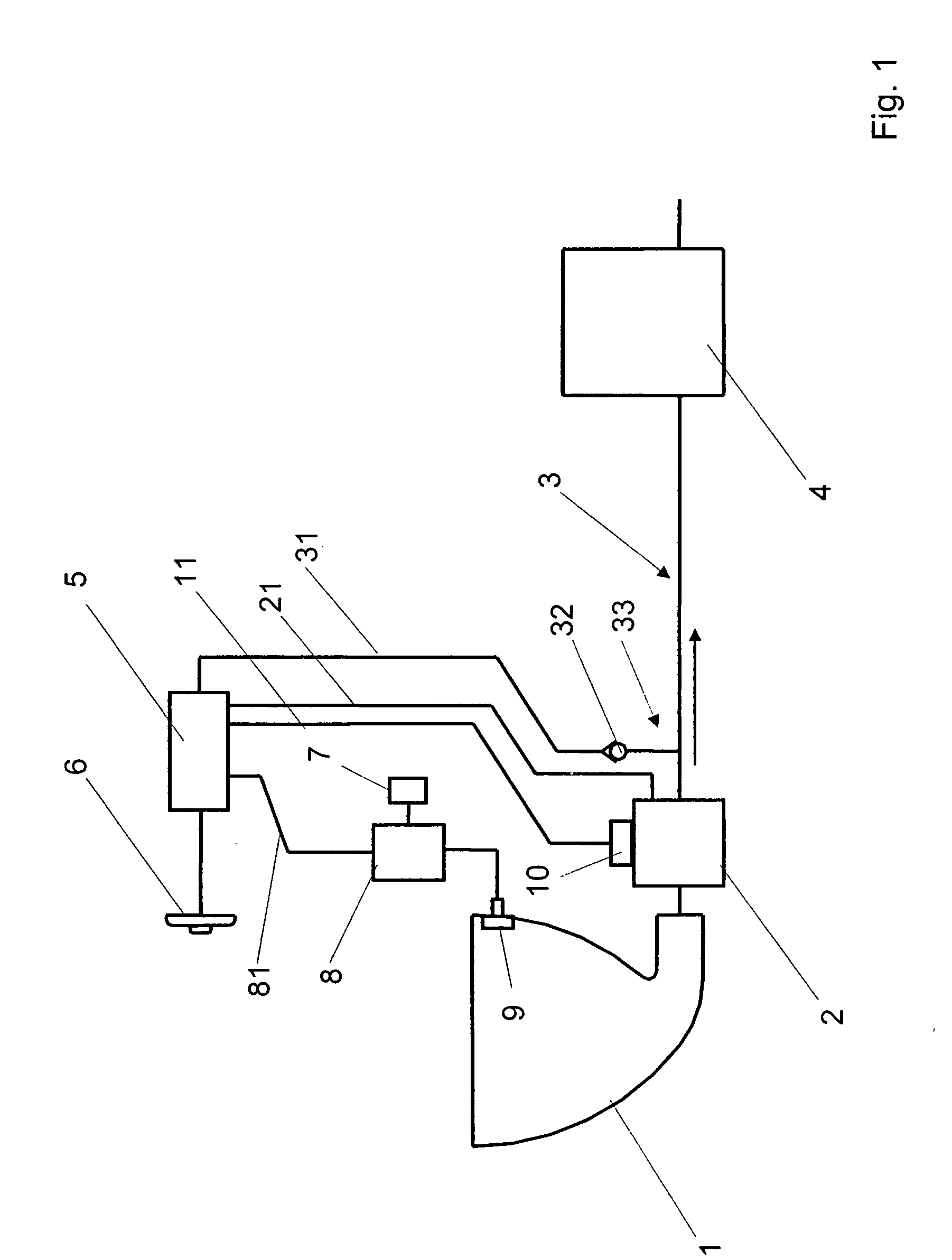
[0023]FIG. 1 illustrates in a general manner an embodiment of a vacuum sewer system comprising a sewage receptacle 1, sewer piping 3 connected to the sewage receptacle 1 by means of a discharge valve 2, and a vacuum generating means 4 for generating vacuum in the sewer piping 3. The vacuum sewer system is provided with a control mechanism 5 for controlling the function of the discharge valve 2. The vacuum sewer system may include a plurality of sewage receptacles with related discharge valves, (water valves), and control mechanisms, whereby the number of vacuum generating means may vary depending upon the layout and size of the whole system.

[0024]Vacuum sewer systems, including vacuum operated discharge valves, vacuum operated water valves, and vacuum control mechanisms, are well known in the art and are not therefore explained in further detail in this conne...


PUM


Abstract

The present invention relates to a sewer system comprising a sewage receptacle (1), sewer piping (3) connected to the sewage receptacle by means of a discharge valve (2), a vacuum generating means (4) for generating vacuum in the sewer piping, and a control mechanism (5) for controlling the discharge valve. In order to achieve a more rapid closing of the discharge valve (2) after discharge of the sewage from the sewage receptacle (1), the vacuum sewer system further comprises an aeration means (10) in direct fluid communication with the discharge valve (2). The control mechanism (5) is arranged to control the aeration means (10). The present invention also relates to a discharge valve (2) for such a vacuum sewer system.

Description

CROSS-REFERENCE TO RELATED APPLICATION[0001]This application claims priority to Finnish Patent Application No. 20065209 filed on Mar. 31, 2006, the contents of which are incorporated herein by reference.BACKGROUND OF THE INVENTION[0002]The present invention relates to a vacuum sewer system comprising a sewage receptacle, sewer piping connected to the sewage receptacle by means of a discharge valve, a vacuum generating means for generating vacuum in the sewer piping, and a control mechanism for controlling the discharge valve, according to the preamble of claim 1. The present invention also relates to a discharge valve for such a vacuum sewer system according to the preamble of claim 11.[0003]In the context of the present invention the sewage receptacle may be e.g. a toilet unit or toilet bowl, urinal, sink, wash basin, shower, etc. The sewage may be black water originating from e.g. a toilet unit or a urinal, or grey water originating from e.g. a sink, wash basin, shower, etc. A rin...

Claims


Application Information

Patent Timeline
Patent Type & Authority Applications(United States)
IPC IPC(8): E03D11/00
CPCE03F1/006E03D9/14E03D11/00E03F1/00E03D5/024
Inventor LAPPALAINEN, VESALINDROOS, GUNNARRONNBLAD, KAJ
Owner EVAC INT
Why Eureka
Try Eureka